


I. INTRODUCTION
As is well-known, linear dipole antennas could be treated as one-dimensional (1D) resonators and they usually suffer from inherent narrow-band properties. When linear dipoles are evolving into conical antennas [Reference Schelkunoff1–Reference Lu, Liu, Tong and Zhu3], broadband designs are obtained. However, smooth profile or tapered structures will be introduced and it will make the analysis and designs more complicated. Therefore, much attempt has been made to design wideband antennas, while maintaining their simple thin/linear profile [Reference Wong and King4–Reference Hsu and Huang10].
Basically, multiple dipoles/radiators can be introduced to the main dipoles so that dual-band [Reference Wong and King4, Reference Kuo and Wong5] and broadband characteristics [Reference Hamid and Hamid6–Reference Hsu and Huang10] are obtained. Most of these additional radiators contribute the same polarization components to the main dipoles [Reference Kuo and Wong5–Reference Hsu and Huang10]. Since all the additional and the main dipoles operate at their dominant modes, i.e. the one half-wavelength mode, this design approach is based on the “single radiator, single mode” idea. Another effective way for wideband/broadband operation is to use non-radiated feed networks [Reference Latif, Shafai and Sharma11–Reference Le and Karasawa15]. The additional tuning stubs [Reference Latif, Shafai and Sharma11, Reference Behdad and Sarabandi12] or integrated baluns [Reference Yang, Chu, Tu and Wang13, Reference Wang, Wu, Yin and Liu14] in the feed network can compensate the reactance of the radiator, and then result in wideband operations. Equivalently, this design approach can be treated as to combine an adjacent, less-radiated parasitic mode to a radiation mode (i.e. the dominant, or one-half wavelength mode), and then lead to a wideband operation in the way of “single radiator, single radiation mode and multiple less-radiated parasitic modes”. The third way for broadband designs is using complementary elements [Reference Luk and Wu16, Reference Lu, Zhang, Tong and Zhu17]. When an electric dipole and a magnetic dipole are properly combined and excited at their dominant radiation modes, the resultant reactance of the composite antenna can be tuned to be nearly zero due to their complementary reactance relation [Reference Luk and Wu16]. Therefore, wideband operation can be realized in the way of “dual radiators, single radiation mode”. However, both the reactance compensation and the complementary dipoles techniques will introduce additional complexities to the antenna.
As a new alternative way, if multiple radiation modes could be excited within a single dipole by introducing less-radiating elements, broadband radiation characteristics could be obtained in a different but simpler way. In this paper, a wideband dipole antenna based on multi-mode wideband filter concept [Reference Zhu, Fu and Wu18–Reference Huang, Cheng and Zhu20] and “single radiator, multiple radiation modes” idea [Reference Lu and Zhu21] is proposed. In a center-fed dipole antenna, a pair of stubs is at first introduced near the two nulls of surface current distribution of the second odd-order mode, i.e. the three halves-wavelength dipole resonant mode. As such, this mode can be excited and perturbed downwards with its first counterpart mode to achieve a wideband radiation with two resonances in the operating band. In this context, the dipole width is still much smaller than its length. By properly adjusting the stub length and dipole width, a wideband, dual-mode dipole antenna with bandwidth of 49.7% can be obtained.
II. OPERATION PRINCIPLE
A center-fed, voltage-driven dipole in free space with length D, width W, and feed gap g and current distribution of its first two odd-order dipole modes, i.e. one half- and three halves-wavelength dipole modes, are depicted in Fig. 1 under S = 0. Then, a pair of stubs with nonzero length S and the same width is symmetrically introduced at the two respective nulls of current distribution of the three halves-wavelength dipole mode. As the length S increases, the resonant frequency of the three halves-wavelength mode could be gradually reduced, while that of the one half-wavelength mode would be rarely perturbed.

Fig. 1. Geometry of proposed stub-loaded dipole antenna and electric current distributions of two resonant modes to be employed.
As shown in Fig. 2, as the stub length S increases, the resonant frequency of the three halves-wavelength mode tends to progressively move downwards, while that of the one half-wavelength is almost unchanged. Next, this dipole antenna is centrally fed by a symmetrical twin-line and its overall structure is formed on a substrate with relative permittivity ε r = 2.65 and thickness h = 1 mm. Using the Zeland's IE3D, frequency response of its reflection coefficient could be numerically calculated. Three sets of results are plotted in Figs 3(a) and 3(b). Under the selection of S = 18.9 mm (i.e. approximately equal to a quarter-wavelength at 2.5 GHz), the two modes could be reallocated in proximity to each other, thus constituting a wide radiation band with two reflection zeros due to two resonant modes [Reference Lu and Zhu21]. When W = 3.6 mm, the input resistance of the antenna is as high as about 400 Ω. As W increases, this resistance would be gradually decreased to 200 and 100 Ω, approaching 50 Ω as highly demanded in practical implementation. Nevertheless, the wideband characteristic is maintained with two resonances in the operating band.

Fig. 2. Variation of resonant frequencies of the two dipole modes with respect to varied stub length S (W = 3.6, g = 0.2, and D = 56.2 mm), (a) reflection coefficient in dB and (b) input impedance.

Fig. 3. Reflection coefficient of the stub-loaded dipoles with respect to width W (S = 18.9, g = 0.4, and D = 82.2 mm), (a) reflection coefficients in dB and (b) impedance curves on Smith chart.
Because only a pair of X-oriented stub is introduced, the antenna is not symmetrical with respect to the Z-axis. An ideal, differentially excited dipole along the Z-axis should exhibit inherent infinite perfect electric conductor (PEC) boundary condition in the XY-plane (i.e. the H-plane) and infinite perfect magnetic conductor (PMC) boundary condition in the YZ-plane (i.e. the E-plane), as shown in Fig. 4(a) [Reference Lu and Zhu21]. The X-oriented current distribution along the stub now becomes asymmetrical with respect to the Z-axis and it will change the dipole's natural PMC boundary condition in the YZ-plane, as shown in Fig. 4(b). Thus the radiation from the stub portion could not be entirely canceled with each other. This phenomenon may tremendously increase cross-polarized component in the XY-plane and may distort the radiation pattern as shown in [Reference Kuo, Chou, Hsu, Chou and Nepa8]. In order to simultaneously maintain the inherent PEC and PMC boundary conditions of a basic dipole and then to suppress the cross-polarization, two pairs of bilateral stubs are symmetrically loaded along the main dipole radiator along the Z-axis as depicted in Fig. 4(c) [Reference Lu and Zhu21]. In this way, the X-oriented currents, I s1 and I s2, are enforced to obey the natural PEC and PMC boundary conditions as described in Fig. 4(a). Thus, the cross-polarized components in the XY-plane can be effectively suppressed.
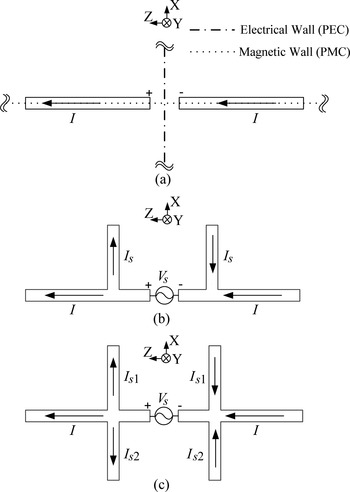
Fig. 4. Surface current distribution analysis of the stub-loaded dipole: (a) the natural boundary condition of an ideal dipole for comparison; (b) the unilateral loaded case; and (c) the bilateral loaded case.
Then, a bilateral loaded dipole is designed and the simulated reflection coefficient, |S 11|, is plotted in Fig. 5 with that of the unilateral loaded dipole for comparison. It is observed that two reflection zeros can be obtained in both cases, thus indicating that the two resonant modes in both dipoles are excited for radiation in a wide operating band.

Fig. 5. Reflection coefficients with reference to 100 Ω source impedance for the unilateral and bilateral stub-loaded dipole antennas with S = 18.9 and 16.9 mm, respectively (W = 11.6, g = 0.4, and D = 82.2 mm).
III. NUMERICAL ANALYSES AND EXPERIMENTAL VALIDATION
In this section, the unilateral and bilateral stub-loaded dipole antennas are respectively, designed, fabricated, and measured to verify the design approach. In order to directly match with 50 Ω coaxial cables, the double-sided printed dipoles are constituted and they are adhesively fed by coaxial cables: The outer conductor of the cable is directly bonded to one arm of the dipole, and the inner one is connected to the another arm. Figure 6 shows the photographs of the two fabricated prototypes. Both sides of the printed antenna are connected with each other by using the 3M's conductive and adhesive copper tapes. The final dimensions of both prototypes are S = 18.9, g = 0.4, D = 82.2, and W = 11.6 mm. For comparison, a conventional double-sided, straight dipole with identical length D, width W, gap width g but S = 0 is used as a “reference antenna”.

Fig. 6. Photograph of fabricated prototypes.
The reflection coefficient of these two antennas is measured by using an Agilent's 8720ET vector network analyzer. As shown in Fig. 7, the measured |S11| agrees quite well with the simulated one. Two resonances could be observed as theoretically predicted before. The measured |S11| is lower than −10 dB over a frequency range from 1.57 to 2.55 GHz for the unilateral loaded dipole and from 1.63 to 2.71 GHz for the bilateral loaded one. Compared with the reference antenna, the fractional bandwidth (FBW) of the proposed antennas has been tremendously increased to 49.7 from 17.0%.
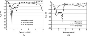
Fig. 7. Simulated and measured reflection coefficients. (a) Unilateral case and (b) bilateral case.
The surface current distribution of the proposed bilateral loaded antenna is simulated by using IE3D and displayed in Fig. 8. It is observed, the current distribution at 1.8 GHz is quite similar to those of one half-wavelength dipoles. The current distribution at 2.7 GHz shows three maxima along the peripheral of the dipole and the stubs. This phenomenon implies the three halves-wavelength mode of the main dipole is excited and perturbed by the stubs.

Fig. 8. Simulated surface current distributions of the bilateral loaded dipole, (a) 1.8 GHz and (b) 2.7 GHz.
The radiation patterns of the two antennas at 1.8, 2.4, and 2.7 GHz are measured by employing a Microwave Vision Group's Starlab near-field antenna measurement system. The two sets of measured results are plotted in Fig. 9 for the unilateral and bilateral loaded dipole antennas. Both antennas have a doughnut-shaped radiation pattern in the YZ-plane (the E-plane) and an omnidirectional one in the XY-plane (the H-plane) when operating at 1.8 GHz. Due to the asymmetrical configuration about the Z-axis, the unilateral loaded dipole exhibits an asymmetrical doughnut pattern at 1.8 GHz. Compared with the unilateral loaded antenna, the bilateral loaded antenna has more stable and less frequency dispersive radiation patterns within the impedance bandwidth. It is seen that the bilateral loaded antenna has much lower cross-polarization level in the XY-plane compared with its unilateral loaded counterpart. This outcome has validated the operation principle that is described on a basis of the current distribution in Fig. 4. It is also observed, the radiation pattern of the bilateral loaded antenna at 2.7 GHz is not a doughnut shape but a three-lobe one instead, which is caused by the radiation of three halves-wavelength mode. Unlike the ideal dipole case discussed in [Reference Kraus and Marhefka22], the spurious radiation of the feed cable will distort the symmetry of the pattern about the Y-axis, and this phenomenon agrees with the measured ones presented in [Reference Schantz23, Reference Guéguen, Thudor and Chambelin24].

Fig. 9. Measured radiation patterns at three frequencies: (a) and (b) YZ- and XY-plane at 1.8 GHz; (c) and (d) YZ- and XY-plane at 2.4 GHz; (e) and (f) YZ- and XY-plane at 2.7 GHz.
Finally, the two antennas’ gain are measured and compared in Fig. 10. It can be seen that both antennas have stable gain frequency response within their impedance bandwidth. The two antennas have average gain of 2.5 and 2.0 dBi and average efficiency of 90 and 88% within their corresponding impedance bandwidth. According to the two antennas’ radiation patterns, polarization purity, gain, and efficiency, it can be figured out that the bilateral loaded dipole should have a better wideband performance in all the aspects. The radiation bandwidth of the bilateral loaded dipole can be determined as the same as its impedance bandwidth, i.e. 1.63–2.71 GHz or 49.7% in FBW.

Fig. 10. Measured gain and efficiency of the two antennas, (a) gain and (b) efficiency.
Based on the experimental results, the proposed antenna is comprehensively compared with other wideband dipole antennas in terms of the length-to-width ratio, the numbers of the radiator and the operation modes, impedance bandwidth, gain/efficiency, and design complexity. As tabulated in Table 1, the operation mechanism of the proposed antenna is different from the others and its profile is still kept to be narrow. In addition, it has the lowest design complexities compared with its counterparts. Under the restriction of the lowest design degree of freedoms, an operational bandwidth of 49.7% with stable radiation characteristics is achieved.
Table 1. Comparison between wideband and multi-arm dipoles.
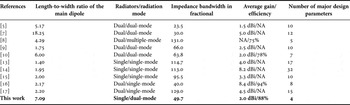
NA, not available. The bold font is to highlight the difference of this work for better comparison.
IV. CONCLUSION
In this paper, a wideband dipole antenna is designed by utilizing the “single resonator, multiple radiation modes” concept. By introducing a pair or two pairs of stubs, the second odd-order dipole mode could be excited and reallocated in proximity to its first order counterpart. Our study indicates that the proposed dual-mode dipole could achieve its impedance bandwidth up to 49.7 against 17.0% in a single-mode antenna. The design approach is described and experimentally validated. Therefore, the proposed approach can be used to explore other types of wideband, multi-mode antennas.
ACKNOWLEDGEMENTS
The authors are indebted to Mrs. H. Bu and Mr. P. Cheong, in University of Macau, for their help in fabrication and test. This work is in part supported by the Multi-Year Research Grants under grant no. MYRG2015-00010-FST & MYRG2014-00079-FST in University of Macau, National Natural Science Foundation of China under grant no. 61471204, 61427801 and Jiangsu Natural & Science Foundation of Universities under grant no. 13KJA510002.
 Wen-Jun Lu received his Ph.D. degrees in Electrical Engineering from Nanjing University of Posts and Telecommunications (NUPT), Nanjing, China, in 2007. He is currently a Professor in Jiangsu Key Laboratory of Wireless Communications, NUPT. He has authored and co-authored over 100 technical papers published in peer-reviewed journals and conference proceedings. He serves as an editorial board member of International Journal of RF and Microwave Computer-Aided Engineering. He is a member of the IEEE. He is the translator of the Chinese version “The art and science of ultra-wideband antennas” (by H. Schantz). He authors the book “Antennas: concise theory, design and applications” (in Chinese). His research interests include printed antennas, wideband antennas and arrays, and antenna theory.
 Lei Zhu received his Ph.D. degree in Electronic Engineering from the University of Electro-Communications, Tokyo, Japan, in 1993. Since August 2013, he has been with the University of Macau, where he is currently a Professor and Head of the Department of Electrical and Computer Engineering, Faculty of Science and Technology. He has authored or co-authored over 265 papers in peer-reviewed journals and conference proceedings. His papers have been cited more than 3380 times with the H-index of 32. He is a Fellow of the IEEE. His research interests include microwave circuits, guided-wave periodic structures, antennas, and computational electromagnetic techniques. Dr., Zhu was an Associate Editor for the IEEE TRANSACTIONS ON MICROWAVE THEORY AND TECHNIQUES (2010–2013) and the IEEE MICROWAVE AND WIRELESS COMPONENTS LETTERS (2006–2012). He was the recipient of the 1997 Asia-Pacific Microwave Prize Award.
 Kam-Weng Tam received his B.Sc. and joint Ph.D. degrees in Electrical and Electronics Engineering from the University of Macau, Taipa, Macao, China, and the University of Macau and Instituto Superior Técnico (IST), Technical University of Lisbon, Lisbon, Portugal, in 1993 and 2000, respectively. Since 1996, he has been with the University of Macau, where he is currently a Professor and the Associate Dean (Research and Graduate Studies) with the Faculty of Science and Technology. He has authored or co-authored over 100 journals and conference papers. His research interests have concerned multifunctional microwave circuits, RFID, UWB for material analysis and terahertz technology. Dr., Tam was interim secretary for the establishment of the Macau Section in 2003. He was the founder of the IEEE Macau AP/MTT Joint Chapter in 2010 and was chair in 2011–2012. He was a member of the organizing committees of 21 international and local conferences.
 Hong-Bo Zhu received his Ph.D. Engineering degrees in Electrical Engineering from Beijing University of Posts and Telecommunications (BUPT), Beijing, China, in 1996. He is currently a Professor in Jiangsu Key Laboratory of Wireless Communications, Nanjing University of Posts and Telecommunications (NUPT). He is currently the Vice President of NUPT. He is the Vice Chairman of SG3 of ITU Radio Communication Bureau (ITU-R). He is a Fellow of Chinese Institute of Electronics (CIE). He has authored and co-authored over 200 technical papers published in peer-reviewed journals and conferences. His research interests include wireless communication theory and propagation in wireless communications.


