


1. Introduction
Turbine energy extraction efficiency in fluid flow has been an area of significant scientific and industrial interest, with Lanchester (Reference Lanchester1915), Betz (Reference Betz1920) and Joukowsky (Reference Joukowsky1920) first deriving an upper bound of energy extraction for a single unconstrained turbine based on actuator disc theory. The classic result, eponymously named the ‘Betz’ or ‘Lanchester–Betz–Joukowsky’ limit, shows that the proportion of the upstream kinetic energy flux that can be usefully extracted (the power coefficient,  $C_P$) is
  $16/27$ of the undisturbed upstream kinetic energy flux through an area equal to the turbine swept area. This is achieved when the flow velocity, normalised on the undisturbed upstream flow speed, reduces to a factor of 2/3 at the turbine plane and to 1/3 in the far wake once the static pressure has recovered to upstream levels. This result has been widely used in engineering practice, including an important extension by Glauert (Reference Glauert1926), which connected an extended theoretical analysis of the quasi-one-dimensional momentum balance with aerofoil lift and drag polar data, and is now widely employed to both analyse the flow field and predict the energy extraction efficiency of real turbines.
Although the Betz limit provides the theoretical limit of power extraction for a single device in an unconstrained flow, beneficial interactions between multiple devices and/or overall flow confinement can be used to constrain the flow to raise this theoretical limit. Garrett & Cummins (Reference Garrett and Cummins2007) extended the actuator disc theory for application to confined flows where the turbines occupy a finite area of the flow passage cross-section. Confinement of the flow may be provided by flow boundaries such as the ground plane, free surface (in the case of tidal stream turbines), the inversion layer (in the case of wind turbines) and/or adjacent turbines. The ratio of the turbine frontal (swept) area relative to the channel cross-sectional area is given by the blockage ratio,  $B$. Garrett & Cummins (Reference Garrett and Cummins2007) showed that this confinement of the flow enabled the extraction of additional power. The maximum extractable power is increased relative to unconfined flow by
  $(1-B)^{-2}$. Performance uplift due to blockage may have significance for tidal stream turbines as they could potentially be arranged to occupy a significant portion of the channel cross-sectional area. It should be noted that blockage effects mean that it is theoretically possible to extract more power than that available in the upstream kinetic flux as there is also a static pressure (or head) drop from far upstream to far downstream of the turbine. This analysis assumes full static pressure equalisation across the channel downstream of the turbine prior to turbulent remixing of the wake. Numerical investigations have shown that the theoretical model broadly agrees with numerical predictions. Turbulent mixing prior to static pressure equalisation can act to increase the limit further (Nishino & Willden Reference Nishino and Willden2012a), implying that the analytical analysis slightly underestimates the power that can be extracted by actuator discs. Extensions of the Garrett & Cummins model have included the influence of free-surface deformation (non-zero Froude numbers) (Whelan, Graham & Peiró Reference Whelan, Graham and Peiró2009; Vogel, Houlsby & Willden Reference Vogel, Houlsby and Willden2016), and the development of an updated blade element momentum theory method for tidal turbines (Vogel, Willden & Houlsby Reference Vogel, Willden and Houlsby2018). Like the Betz limit, the maximum
  $C_P$ for the Garrett & Cummins (Reference Garrett and Cummins2007) model occurs when the wake velocity coefficient is
  $1/3$. This result was only shown numerically in the original paper. For completeness we confirm this result algebraically in Appendix A.
A blockage effect can also be exploited by arrays of turbines, where the flow through a given turbine is further blocked on a local scale due to the proximity of adjacent turbines. By locally capitalising on the blockage effect the Betz limit can be surpassed. As large arrays of turbines are becoming more common in wind engineering and are needed in tidal to make a significant contribution, the optimal layout of these is clearly of interest. Nishino & Willden (Reference Nishino and Willden2012b) explored this idea through an extension of the work of Garrett & Cummins (Reference Garrett and Cummins2007) to consider a two-scale model. They assumed that an array of discs occupied part of the channel and that the local flow passing through and around the discs mixed on a length scale much shorter than the mixing between the flow through the array and the flow bypassing the array. Thus the analysis depends on two blockages: a global blockage (swept area of turbines divided by the cross-sectional area of the channel) and a local blockage (turbine swept area divided by the cross-sectional area of the turbine's local flow passage). This two-scale model showed that for a given total turbine swept area (global blockage) there exists an optimum local blockage. An important limiting case was where the global blockage goes to zero. In this case, it was shown that local blockage effects can enhance the power coefficient to  $0.798$ of the upstream kinetic energy flux. The scale-separation effect has been demonstrated experimentally using porous discs (Cooke et al. Reference Cooke, Willden, Byrne, Stallard and Olczak2015) and is starting to be applied in the wind industry, whilst power uplift through constructive interference in short fences of turbines has been demonstrated in large laboratory experiments (McNaugton et al. Reference McNaugton, Cao, Vogel and Willden2019). Cooke, Willden & Byrne (Reference Cooke, Willden and Byrne2016) further progressed the theoretical analysis by introducing an additional third scale; in this case the globally unblocked
  $C_P$ increases to
  $0.865$.
Accounting for the effects of arrangement on mass flux and general dynamic balance is also important. The inclusion of the blockage effects on large scales in both tidal channels (Vennell Reference Vennell2010) and wind farms (Bleeg et al. Reference Bleeg, Purcell, Ruisi and Traiger2018) have illustrated the importance of considering the impact of blockage on the mass flux of the upstream flow. The efficiency of arrays of energy extraction devices can be diminished by a global choking effect which reduces the mass flux through the channel and the devices. Vennell (Reference Vennell2010) combined a mass-flux model with the blocked flow model of Garrett & Cummins (Reference Garrett and Cummins2007), finding that the interaction between a tidal turbine and the channel dynamics leads to a departure from the Garrett & Cummins (Reference Garrett and Cummins2007) and Betz (Reference Betz1920) models, which predicted achieving maximum power by tuning the wake velocity to 1/3 of the free-stream flow. Optimal ‘tunings’ were instead found to increase monotonically with global blockage ratio, approaching unity for turbines which spanned close to the entire channel cross-section. This analysis was extended by Vennell (Reference Vennell2011) to consider multiple arrays of turbines by locating the updated power optima depending on the channel characteristics, and has been further applied to practical tidal turbine arrays to consider the broader possibility of exceeding the Betz limit (Vennell Reference Vennell2013). For a review of other extensions of actuator disc theory see Adcock et al. (Reference Adcock, Draper, Willden and Vogel2021).
The aim of this paper is to derive a fundamental limit for power extraction and understand the underlying fluid mechanics. Early work has shown that a single side-by-side row outperforms staggered or multi-row arrays (Draper & Nishino Reference Draper and Nishino2014; Hunter, Nishino & Willden Reference Hunter, Nishino and Willden2015) so the focus here is on a large single row array. In this study we extend the theoretical analyses of Nishino & Willden (Reference Nishino and Willden2012b) and Cooke et al. (Reference Cooke, Willden and Byrne2016) to consider  $n$-scales with particular interest in the behaviour as
  $n\to \infty$. The use of multiple scales will be used to explore the array arrangement for optimal power extraction. Alternative interpretations of the present analysis are also possible. For example, self-similarity across scales could be interpreted as a single device with non-uniform resistance. The problem is formulated following the previous analyses and solving the equations numerically. Specifically, by making use of the constructive interference effects of local blockage over multiple scales, we attempt to characterise the optimal multi-scale energy extraction device through a detailed description of the optimal distributions of velocity tuning parameters and local blockage ratios, alongside discussion of the distribution of thrust and power coefficients across the scales. Similarly to the aforementioned studies, we assume that the mass flux through the channel is constant. We provide a physical explanation as to how multiple scales, and specifically wake remixing, leads to an increase in extractable power.
2. Array model
The formulation of the model problem is conceptually the same as that in the previous study of Cooke et al. (Reference Cooke, Willden and Byrne2016) extended to an arbitrary number of scales. A frontal view of a  $n=4$-scale extractor is shown in figure 1, where the fractal nature of the arraying is made clear, and from which an arbitrary-scale extractor may be visualised. An alternative interpretation of the configuration is a single row of discs in a channel sub-arrayed an arbitrary number of times.
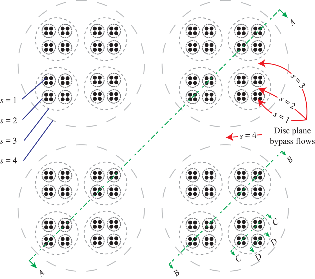
Figure 1. An illustration of the frontal view of an  $n=4$-scale model where each subsequent scale consists of sub-division into
  $d=4$ discs. The resultant configuration of discs (the inner
  $s=1$ scale) is drawn with black circles, and each larger dashed ring represents a new, larger, scale. The accelerated bypass flows at the disc plane at each scale are shown, and sections spanning the first
  $4$ scales, over which the relevant flow equations are solved, are shown in detail in figure 2.
Consider an  $n$-scale flow problem schematically illustrated in figure 2, where the first
  $(s=1)$ scale denotes the smallest innermost (disc) scale and the
  $s=n$th scale denotes the largest outermost scale. Consider first a side-by-side row of equally spaced actuator discs as shown in figure 2(c). Mass, linear momentum and inviscid energy conservation relations may be written to relate the flow conditions, namely the static pressure and axial flow velocity (other flow components being neglected), at each of the stations 1–4 through both the core (flowing through the disc) and bypass regions as a function of the inter-disc spacing (local blockage). These relations, which account for finite blockage, here present due to the adjacent discs as well as sea bed and surface proximity, are an extension on the classic Betz actuator disc model (see Appendix A for details). The actuator exists between stations 2 and 3 across which the flow velocity is continuous but a discontinuous drop in pressure occurs. Downstream of the actuator the flow decelerates allowing pressure recovery in the core flow until the static pressure equilibrates with the accelerated bypass flow at station 4. Turbulent mixing is then assumed to occur between the bypass and core flows such that the static pressure and flow velocity fully equalise by station 5, with the flow velocity necessarily recovering to the inflow condition at station 1 (by mass conservation), and the pressure at 5 being less than at 1 due to the finite blockage effect.
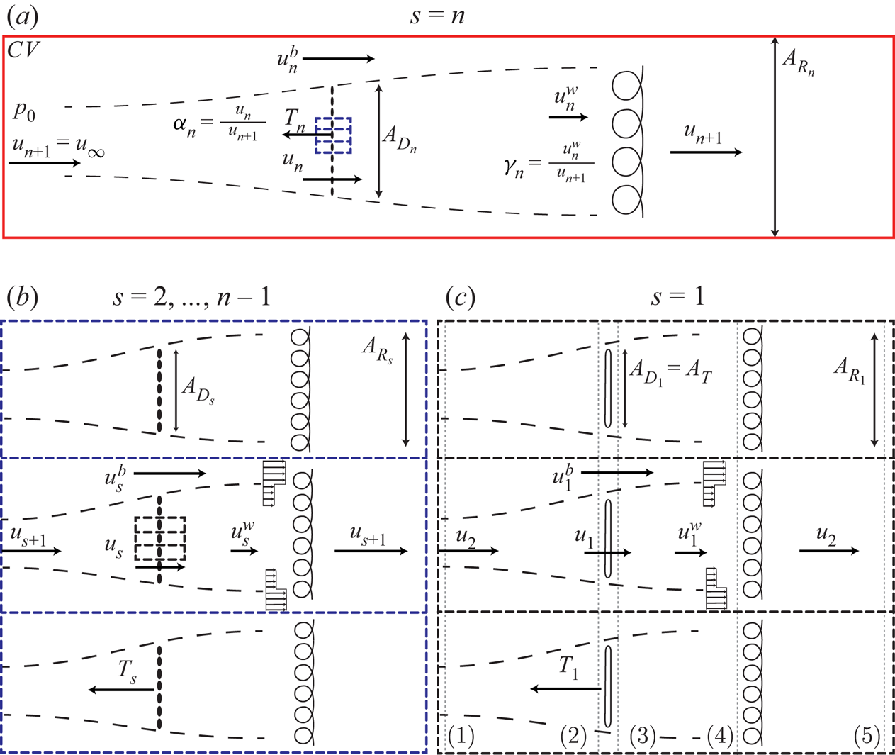
Figure 2. A plan-view realisation of a multi-scale array in a wide and shallow channel (as might occur for a tidal channel), with key parameters shown. The scales  $s$ are ordered from the smallest scale
  $(s=1)$ to the largest scale
  $(s=n)$. The largest scale (a) consists of an array of devices (which is the plan-view realisation of section
  $A$-
$A$- $A$ in figure 1), with each device subsequently broken down into further arrays of devices until the smallest scale which extracts power through actuator discs (c) (plan-view realisation of section
  $D$-
$D$- $D$ in figure 1). Intermediate scales are shown in (b) (plan-view realisation of sections
  $B$-
$B$- $B$ or
  $C$-
$C$- $C$ in figure 1).
We next consider the two-scale problem (Nishino & Willden Reference Nishino and Willden2012b) in which a large number of discs are arrayed in a side-by-side configuration in a single row in an infinitely wide (unblocked) channel; see figure 2(a) with  $n=2$. There are a large but finite number of discs in the row so that we may assume homogeneous behaviour across the array. The flow picture at this outer scale is analogous to the inner-scale flow problem and we may write mass, momentum and energy conservation equations for this outer scale in a similar way to those for the inner scale. The inner and outer scales are kinematically and dynamically coupled so that the flow velocity decelerates from
  $u_{n+1}$ upstream of the outer scale, to
  $u_n$ at the extraction plane of that scale which is co-located with the upstream condition of the inner scale. Downstream of the inner-scale actuators, recovery and mixing with the inner-scale bypass flow enables the flow velocity to recover to
  $u_n$, which is compatible with the flow velocity downstream of the array of the outer scale in figure 2(a). Dynamic coupling is achieved by requiring that the thrust force exerted by the actuator discs of the inner scale be equal to the force exerted at the extraction plane at the outermost scale. Mass, momentum and energy equations for the two scales may then be solved numerically.
Now assume that there are multiple disc rows, again all in a side-by-side configuration, of the type shown in figure 2(a), and that these are further arrayed as in figure 2(b), where each row of discs is now equally spaced apart. The model requires that there are a large, but finite, number of discs in each row, and a large, but finite, number of disc rows at the next scale, such that we may consider discs and disc rows to be homogeneous across their scale of the model. At this larger scale, the flow problem looks similar to that of the disc ( $s=1$) scale. Analogous to the physics governing the disc scale therefore, conservation laws are used to dictate the relationship between inter-array spacing and flow velocities. This process can be repeated to construct larger and larger scales, each with a scale-specific spacing between the arrays at that scale. The resultant device, shown in figure 2(a), is once again analysed through the same set of equations (see Appendix A). Rather than being confined by adjacent discs (as at the smallest scale) or adjacent arrays (as at all other scales), the largest
  $s=n$-scale device may be analysed both in an unbounded flow, as in the Betz actuator disc model, or in a bounded flow, as in the case of tidal turbines arrayed in a finite dimension channel. In either case the model assumes that the far upstream flow remains unaffected by the resistance presented by the disc array. This assumption is clearly only valid in the limit of vanishing resistance relative to flow inertia and will be explored later in the context of unbounded arrays.
The flow problems at each scale may be solved under the assumption that the static pressure and velocity (through turbulent mixing) fully equalise prior to mixing with the subsequent scale. For this assumption to hold the number of devices and sub-arrays at every scale needs to be sufficiently large (Nishino & Willden Reference Nishino and Willden2013). In addition to the kinematic and dynamic coupling between scales, they are additionally coupled geometrically; the number and spacing of the discs in figure 2(c) dictates the size of each array in figure 2(b). This allows for closure of the flow problem in terms of the thrust applied by each actuator disc at the smallest (figure 2c) scale, the spacing between the discs/arrays at each scale, and the global blockage. In particular, this paper focuses on maximising the power extraction
 \begin{equation} C_{P_1}=\frac{P_1}{\frac{1}{2}\rho u_2^3 A_T}=\frac{T_1 u_1}{\frac{1}{2}\rho u_2^3 A_T}, \end{equation}
as a function of the optimal arrangement of discs/arrays at each scale, with  $P_1=T_1 u_1$ the power generated by the inner-scale actuator disc of area
  $A_T$.
Non-dimensional velocity induction factors are first defined for each scale such that
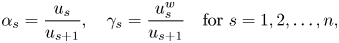 \begin{equation} \alpha_s=\frac{u_{s}}{u_{s+1}}, \quad \gamma_s = \frac{u^w_s}{u_{s+1}} \quad \textrm{for} \ s=1,2,\ldots, n, \end{equation}
where the subscript  $s$ denotes the scale number,
  $w$ denotes the wake flow and
  $u_{n+1}=u_\infty$ is the assumed undisturbed velocity upstream of the multi-scale array (see figure 2). The assumption of a completely undisturbed velocity upstream is strictly only true in the case of vanishingly small disc resistance relative to flow inertia.
Blockage ratios at each scale are likewise defined as an area ratio
 \begin{equation} B_s=
\frac{A_{D_s}}{A_{R_s}} = \frac{\textrm{Local frontal area of the }
s\textrm{-scale device}}{\textrm{Local representative passage area}} \quad \textrm{for} \ s=1,2,\ldots, n,
\end{equation}
\begin{equation} B_s=
\frac{A_{D_s}}{A_{R_s}} = \frac{\textrm{Local frontal area of the }
s\textrm{-scale device}}{\textrm{Local representative passage area}} \quad \textrm{for} \ s=1,2,\ldots, n,
\end{equation}
where the numerator represents the cross-sectional area of the device at any given scale (i.e. the turbine swept area at the smallest scale and the entire device area at the largest scale), and the local representative passage area represents the cross-sectional area of the flow passage around a single device at that scale (i.e. the flow passage encompassing an individual turbine's core and bypass flows at the smallest scale and the entire channel at the largest scale). Note that  $B_n \to 0$ in the case of an infinitely wide channel (implying globally unblocked flow).
The thrust coefficients at each individual scale may now be written out as a function of the velocity induction factor and blockage through the consideration of conservation of mass, momentum and energy in quasi-one-dimensional form (see Nishino & Willden (Reference Nishino and Willden2012b) for further details)
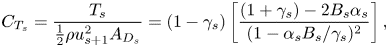 \begin{equation} C_{T_s}=\frac{T_s}{\frac{1}{2}\rho u_{s+1}^2 A_{D_s}}=(1-\gamma_s)\left[\frac{(1+\gamma_s)-2B_s\alpha_s}{(1-\alpha_s B_s/\gamma_s)^2}\right], \end{equation}
where the wake induction factor  $\gamma _s$ is related to
  $\alpha _s$ through
 \begin{equation} \alpha_s=\frac{1+\gamma_s}{1+B_s+\sqrt{(1-B_s)^2+B_s(1-1/\gamma_s)^2}}. \end{equation}
Each scale can now be solved for simultaneously through kinematic coupling of the velocity and dynamic coupling through the balance of the net thrust force at all scales
 \begin{equation} C_{T_s}=\frac{d_{s-1} T_{s-1}}{\frac{1}{2}\rho u_{s+1}^2A_{D_s}}=\alpha_{s}^2B_{s-1} C_{T_{s-1}} \quad \text{for}\ s=2,3,\ldots, n , \end{equation}
where  $d_s$ is the number of devices at any given scale (and
  $d_n=1$ always). The scales are hence coupled both geometrically by
  $d_s A_{R_s}=A_{D_{s+1}}$ and dynamically by
  $d_s T_s = T_{s+1}$.
In particular, following the same formulation as in Appendix A, for  $n$-scales, the flow problem can hence be re-cast as the following nonlinear optimisation problem:
 \begin{equation} \textrm{max}\,C_{P_G}(\gamma_1,\gamma_2,\ldots,\gamma_n,B_1,B_2,\ldots,B_{n-1},B_G) =\alpha_1 C_{T_1} \prod_{s=2}^n\alpha_s^3, \end{equation}
where the expression for the global power coefficient  $C_{P_G}$ follows from (2.1), with
  $C_{P_G}$ normalised by the upstream flow velocity
  $u_{n+1}$ and the disc area
  $A_T$. As a consequence of the dynamic coupling in (2.6), the objective function is subject to the following
  $n-1$ constraints:
 \begin{equation} \displaystyle C_{T_j}=C_{T_1}\prod_{s=2}^{j} \alpha_s^2 B_{s-1} \quad \text{for}\ j=2,3,\ldots, n , \end{equation}
where  $C_{T_s}$ is given by (2.4) and
  $\alpha _s$ by (2.5) for
  $s=1,2,\ldots ,n$.
Finally, the solution domain is physically constrained by  $0 \leqslant \gamma _s \leqslant 1, 0 \leqslant B_s \leqslant 1$. Note that for an infinitely wide channel
  $(B_n\to 0)$, the constraints on
  $\alpha _n$ and
  $C_{T_n}$ reduce to
  $\alpha _n=(1+\gamma _n)/2$ and
  $C_{T_n}=(1-\gamma _n)(1+\gamma _n)$ respectively.
As in Appendix A, the Lagrangian for the multi-scale problem is now written as
 \begin{equation} \mathcal{L} = \alpha_1 C_{T_1} \prod_{s=2}^n\alpha_s^3 - \sum_{k=1}^{n-1} \lambda_k \left(C_{T_{k+1}} - C_{T_1}\prod_{j=1}^{k} \alpha_{j+1}^2 B_{j}\right), \end{equation}
where solutions to  $\boldsymbol {\nabla } \mathcal {L}=0$ can be solved numerically for any given
  $n$.
$n$.
For a given  $n$ and
  $B_G=\prod _{s=1}^n B_s$, the multi-scale problem therefore consists of
  $3n-2$ variables to optimise, namely
  $\gamma _s$ for
  $s=1,\ldots , n$ and
  $B_s$ and
  $\lambda _s$ for
  $s=1, \ldots , n-1$. These can be substituted into the objective function (2.7) to locate the optimal global power coefficient. The thrust coefficient and the velocity induction factor at each scale can be calculated with (2.4) and (2.5) respectively. Finally, scale (local) power coefficients can be found by evaluating
 \begin{equation} C_{P_s}=\alpha_s C_{T_s}, \end{equation}
with additional global variables of interest including the global velocity induction
 \begin{equation} \alpha_G(n)=\frac{u_1}{u_{n+1}}=\prod_{s=1}^n \alpha_s, \end{equation}
the device blockage ratio
 \begin{equation} B_D(n)=\prod_{s=1}^{n-1} B_s, \end{equation}
the global velocity tuning factor
 \begin{equation} \gamma_G(n)=\prod_{s=1}^{n} \gamma_s \end{equation}
and the global thrust coefficient
 \begin{equation} C_{T_G}=C_{T_1} \prod_{s=2}^n \alpha_s^2. \end{equation}
 The turning points of (2.9) were solved for numerically for  $n \leqslant 100$, with the results of these computations discussed in § 3. The optima were solved for using an interior point algorithm for nonlinear programming of non-convex functions described in Byrd, Hribar & Nocedal (Reference Byrd, Hribar and Nocedal1999), where quasi-Newtonian approximations of the objective function are numerically determined for the first and second derivatives. To ensure convergence to a non-local optimum, a global optimisation search described in Ugray et al. (Reference Ugray, Lasdon, Plummer, Glover, Kelly and Marti2007), where the solution space is seeded with trial points, is used in conjunction with the interior point algorithm. The algorithm can be validated by testing against the
  $n=2$ (Nishino & Willden Reference Nishino and Willden2012b) and
  $n=3$ (Cooke et al. Reference Cooke, Willden and Byrne2016) cases, and returns the same solutions cited in the literature. We have also compared this algorithm against alternative formulations of the problem and obtained consistent results.
3. Numerical results
3.1. Performance of a multi-scale device in an infinitely wide channel
We start by presenting results for the case of an infinitely wide channel  $(B_n\to 0)$, which is slightly simpler than the finite global blockage case. The optimal global power coefficient for an
  $n$-scale energy extraction device is plotted in figure 3. An analytic curve fit approximation to the optima, with the relative percentage error shown in figure 3(b), is suggested to be
 \begin{equation} C_{P_G,{{Max}}} (n) = \frac{C_{P,\textit{Betz}}-1}{n}+1, \end{equation}
where  $C_{P,\textit{Betz}}$ is the Betz limit of
  $16/27$. Note that the function is concave for all
  $n>1$, is always a lower bound on the numerical optima, and that
 \begin{equation} \lim_{n\to\infty} C_{P_G,{{Max}}}(n) = 1, \end{equation}
showing that the optimal efficiency of a multi-scale energy extraction device which makes use of constructive interference (local blockage) in an unbounded fluid is 100 % of the undisturbed kinetic energy flux through the device area.
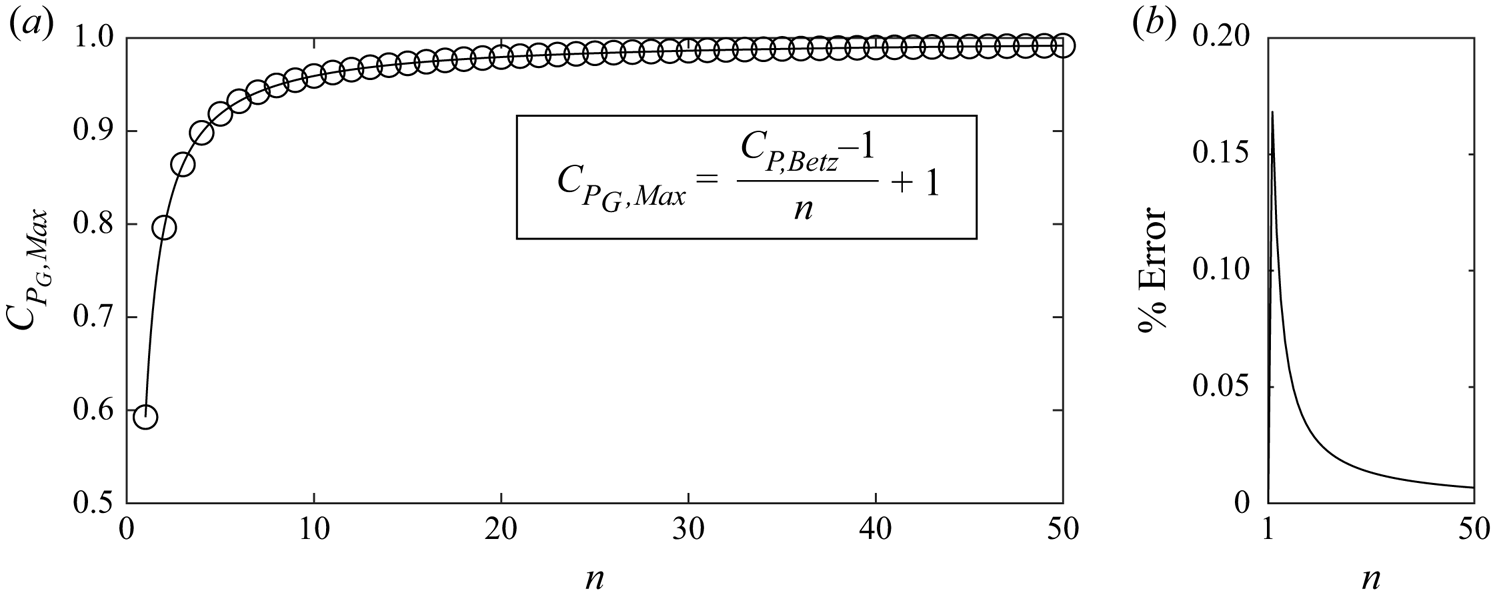
Figure 3. The maximum power coefficient for a multi-scale device in an infinitely wide channel, here shown for all scales to  $n\leqslant 50$. (a) The circles indicate the numerical solutions, and the solid line gives an analytical approximation to the optimal
  $C_P$. (b) The relative percentage error between the approximation and numerical solution.
Of particular interest is why the maximum power extraction asymptotes to a  $C_{P_G}$ of unity, whether this is the maximum for any energy extraction device, and how the properties of the multi-scale energy extraction device are distributed across the scales. The following discussion addresses these questions.
3.2. Properties of optimal unbounded multi-scale devices
For the case of an infinitely wide channel  $(B_n\to 0)$, the theoretical upper bound of energy extraction is limited by
  $C_{P_G}^*=1$ as the static pressure upstream and downstream of the device must be the same. The only energy that can therefore be extracted must be derived from the upstream kinetic flux, which is analogous to the single-scale unblocked energy extractor considered by Betz. In the limit, the multi-scale device clearly approaches this limit of energy extraction in an unbounded steady fluid. This section clarifies the physics of the convergence to this optimal condition for large
  $n$.
$n$.
For the single-scale Betz-like device, increasing the static pressure drop across the device by increasing the resistance to the flow comes at the cost of modifying the upstream stream-tube area. Additional scales allow for a decoupling of these two phenomena, and as the total number of scales becomes large, these conditions, namely the optimal static pressure drop across the device and no outer stream-tube modification can be simultaneously realised. At large  $n$, the smallest scales are able to achieve blocked flow conditions, and can remove power with essentially no local flow divergence (hence large kinetic efficiency). At the same time, the entire array is becoming infinitely large, such that
  $B_D$ tends to zero and so the discs at the smallest scale cannot cause large-scale flow diversion. Numerical evidence is presented to illustrate the convergence to these two optimal conditions.
Figure 4(a) illustrates the convergence of  $\alpha _G$ to
  $1/2$ for large
  $n$, allowing for an optimal pressure drop, normalised on the upstream dynamic pressure
  $\rho u_\infty ^2/2$, of
  $\varDelta c_p^*=2$ across the smallest scale of the device. Figure 4(c) likewise illustrates the convergence of
  $\alpha _n\to 1$, implying that the stream-tube area remains unmodified at the largest scale without violation of the velocity constraint, namely that the velocity reduction factor in the far wake,
  $(1-\gamma _n)$, is twice the disc plane's reduction factor,
  $(1-\alpha _n)$.
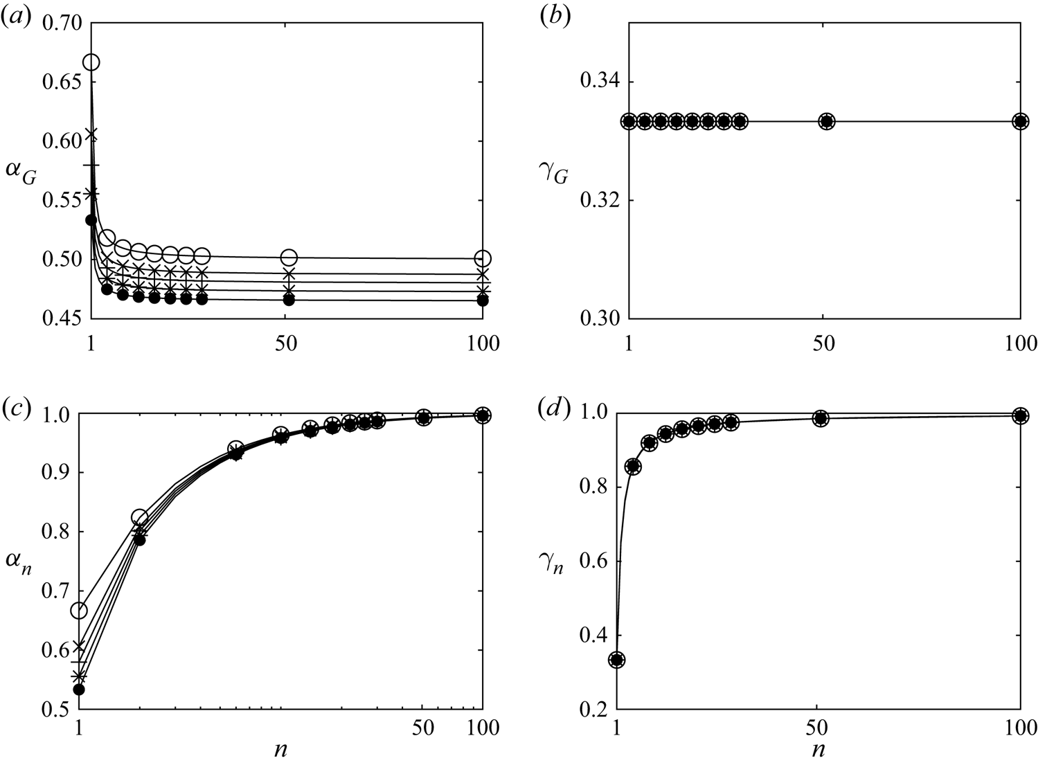
Figure 4. Global parameters exhibiting convergent behaviour for large  $n$ (markers indicating numerical solutions with circles for
  $B_G = 0$, crosses for
  $B_G = 0.1$, pluses for
  $B_G = 0.15$, stars for
  $B_G = 0.2$ and filled circles for
  $B_G = 0.25$; every fourth simulated data point plotted). (a) The global velocity induction factor
  $\alpha _G$, (b) the wake tuning velocity factor
  $\gamma _G$, the velocity factors at the largest scale (c)
  $\alpha _n$ (logarithmic scale for
  $x$-axis) and (d)
  $\gamma _n$.
In the limit as  ${n\to \infty }$, the multi-scale energy extraction device therefore approaches the theoretical upper bound of energy extraction from an unbounded fluid, by simultaneously maximising the pressure drop across the discs at the smallest scale, and leaving the stream-tube unmodified at the largest scale. The distributions of the parameters that maximise the power extraction for an
  $n=100$ multi-scale device are shown in figure 5, as a close approximation for the limiting behaviour of an optimal (infinite-scale) device. Figure 5(a,b) demonstrates the gradual deceleration of the flow across each scale, with all
  $\gamma _s$ and
  $\alpha _s$ nearing unity, and with the locally normalised static pressure drop gradually (and optimally) building up to the smallest scale (figure 5c). The distribution of the local blockage ratios, shown in figure 5(d), satisfies the optimal constraints on velocity and static pressure drop, with the blockage approaching near unity at the smallest scale. Figure 6 likewise shows the distribution of Lagrangian multipliers across scales, giving indication of the relative importance of a given thrust constraint between consecutive scales. This illustrates the relative decoupling of the critical thrust constraint at the largest (stream-tube) scale and the constraints between the smallest (pressure-drop) scales. In the limit, the thrust constraint on the smallest scale becomes negligible
  $(\lambda _1\to 0)$, and the smallest scale therefore decouples. All of the intermediate scales allow the flow to achieve both outer and inner-scale optima subject to the physical constraints of the system. Variations in the constraint at the largest scale dictate the energy capture of the entire device; changes in outer-scale blockage will therefore have a significant impact on the energy extraction efficiency.
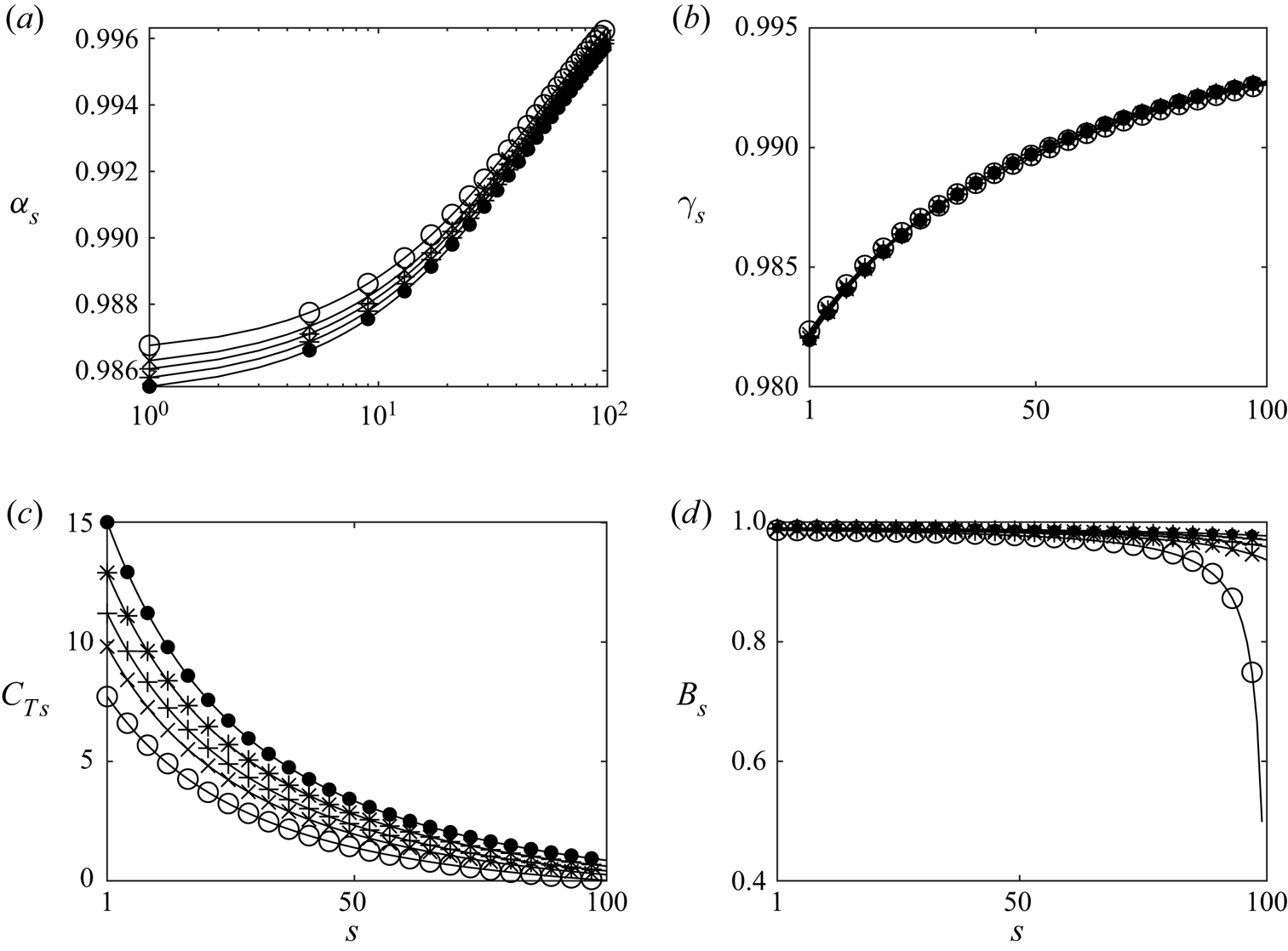
Figure 5. The solution for an  $n=100$ multi-scale energy extraction device illustrating the approximate limiting behaviour of an infinite-scale device (markers indicating numerical solutions with circles for
  $B_G = 0$, crosses for
  $B_G = 0.1$, pluses for
  $B_G = 0.15$, stars for
  $B_G = 0.2$ and filled circles for
  $B_G = 0.25$; every fourth simulated data point plotted). The velocity induction factors (a)
  $\alpha _s$ (logarithmic scale for
  $x$-axis) and (b)
  $\gamma _s$, (c) the scale thrust coefficients
  $C_{T_s}$, (d) the local blockage ratios
  $B_s$, are shown for all scales
  $1 \leqslant s \leqslant 100$.
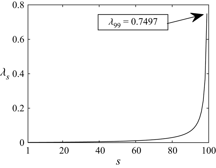
Figure 6. Lagrangian multiplier,  $\lambda _s$, distribution across scales,
  $1 \leqslant s \leqslant n-1$, for an
  $n=100$ unbounded multi-scale device.
Additional observations on the limiting parameters can be made with the aid of the governing equations, constraints and numerics. Consider a substitution of the constraints (2.8) into the objective function (2.7)
 \begin{equation} C_{P_G} = \frac{\alpha_1 C_{T_j}\prod\limits_{s=2}^n \alpha_s^3}{\prod\limits_{s=2}^{j} \alpha_s^2 B_{s-1}}, \end{equation}
which is true for all  $j\geqslant 2$. By considering the large-scale constraint
  $j=n$, we can write
 \begin{equation} C_{P_G} = \frac{(1-\gamma_n)(1+\gamma_n)}{\prod\limits_{i=1}^{n-1} B_i}\prod_{i=1}^n \alpha_i. \end{equation}
As the number of scales becomes large  $(n\to \infty )$, the optimal induction factor at the outermost scale becomes
  $(1-\alpha _n)\to 0$. This condition is logical for optimal extraction as in the limit it implies that, by mass conservation, no flow is diverted around the device. Additionally, by considering the constraint on velocity at the largest scale, this implies that
  $(1-\gamma _n)\to 0$. Substituting these optimal conditions into (3.4) allows for a consideration of the individual terms of the power coefficient
 \begin{equation} C^*_{P_G}=\lim_{\gamma_n\to1} \frac{(1-\gamma_n)(1+\gamma_n)}{\prod\limits_{i=1}^{n-1} B_i}\prod_{i=1}^n \alpha_i, \end{equation}
where for large  $n$ we observe numerically that the optimal
  $\alpha _G$ for energy extraction is (see figure 4a)
 \begin{equation} \lim_{n\to\infty} \prod_{i=1}^n \alpha_i = \alpha_G =\frac{1}{2}. \end{equation}
For the maximum  $C_{P_G}$ to be equal to the upper bound of 1, we must therefore have
 \begin{equation} (1-\gamma_n)\sim \prod_{i=1}^{n-1} B_i= B_D\end{equation}
and
 \begin{equation} \lim_{n\to\infty} \prod_{i=1}^{n-1} B_i = 0, \end{equation}
which is confirmed by the numerical results. Considering the final constraint, we can also show that
 \begin{equation} (1-\gamma_n)(1+\gamma_n)=C_{T_1}\prod_{i=2}^n \alpha_i^2 B_{i-1}, \end{equation}
so that for large  $n$
$n$
 \begin{equation} \lim_{n\to\infty} C_{T_1} = \lim_{n\to\infty} \left(\frac{(1-\gamma_n)}{\prod\limits_{i=1}^{n-1}B_i}\frac{\alpha_1^2(1+\gamma_n)}{\prod\limits_{i=1}^n\alpha_i^2}\right) = \frac{2\alpha_1^2}{\left(\dfrac{1}{2}\right)^2}=8\alpha_1^2, \end{equation}
from which it is clear that to maximise the objective function (2.7), the product  $\alpha _1 C_{T_1}$ is maximised (and
  $C_{P_G}\to 1$) when
  $\alpha _1$ tends to
  $1$ as
  $n\to \infty$. This shows that
  $\lim _{n\to \infty } C_{T_1}=8$, which can clearly be observed in figure 5(c). The constituent components for optimal energy extraction are therefore
 \begin{equation} C_{P_G}^* = \alpha_1^* C_{T_1}^* \prod_{i=2}^n \left(\alpha_i^*\right)^3 = 1 \times 8 \times \left(\tfrac{1}{2}\right)^3 = 1, \end{equation}
where  $\alpha _1^*=1$ physically represents (through mass conservation) the lack of inner stream-tube modification (note that
  $B_1\to 1$ also),
  $C_{T_1}^*=8$ (normalised on
  $1/2\rho u_2^2)$ represents the optimal thrust (or alternatively the pressure drop
  $\Delta c_p^*=2$ normalised on
  $1/2\rho u_\infty ^2$) upon extraction and
  $\alpha _G^*=1/2$ the optimal deceleration of the potential flow upstream of the extraction plane. The convergence to all of these conditions is observed in the numerical results. In the limiting case, therefore, a multi-scale energy extraction device approaches this upper bound of energy extraction without violation of conservation laws, providing a new theoretical limit of energy extraction from a steady unbounded fluid.
The condition that  $(1-\gamma _n)=0$ as
  $n\to \infty$ also implies that
 \begin{equation} \lim_{n\to\infty} C_{T_n} = 0, \end{equation}
i.e. the thrust coefficient when referenced to the area of the  $n\textrm {th}$-scale device tends to zero, whilst the global thrust coefficient
  $C_{T_G}$, which is referenced to actuator disc area, must of course remain non-zero. That
  $C_{T_n} \to 0$ is of particular interest to the mass-flux and blockage coupling considerations in both tidal and wind engineering flows. In a head driven system, resistance to the flow will reduce the mass flux through the system (see Vennell Reference Vennell2010), with that reduction being a function of both the large-scale blockage and thrust. The limiting behaviour of the multi-scale device, namely that
  $C_{T_n}\to 0$ and that
  $B_D\to 0$ removes the impact on the flux through the system. In the limit, therefore, the assumption that the mass fluxes far upstream and downstream of the energy extracting device are equal is implicit to the model for the case of an infinitely wide channel.
3.3. Fractal approximation to unbounded multi-scale devices
We stress here that, although the multi-scale device approaches the optimal conditions for energy extraction, it is not necessarily the only method of optimal extraction. Other device configurations which satisfy the unmodified stream-tube at largest scale, optimal pressure drop at smallest scale and conservation law constraints remains an open question, and further investigations into satisfying these constraints could uncover both novel and practical methods for extracting power above the Betz limit.
A simple example of this which helps aid in the visualisation of a multi-scale device, is a fully fractal arrangement where the local blockage remains the same across all scales, i.e.  $B_L=B_s$ for
  $1\leqslant s \leqslant n-1$. Figure 7 demonstrates that such an array does not significantly under-perform the optimal arrangement, with the large and small-scale constraints also decoupling in the limit.
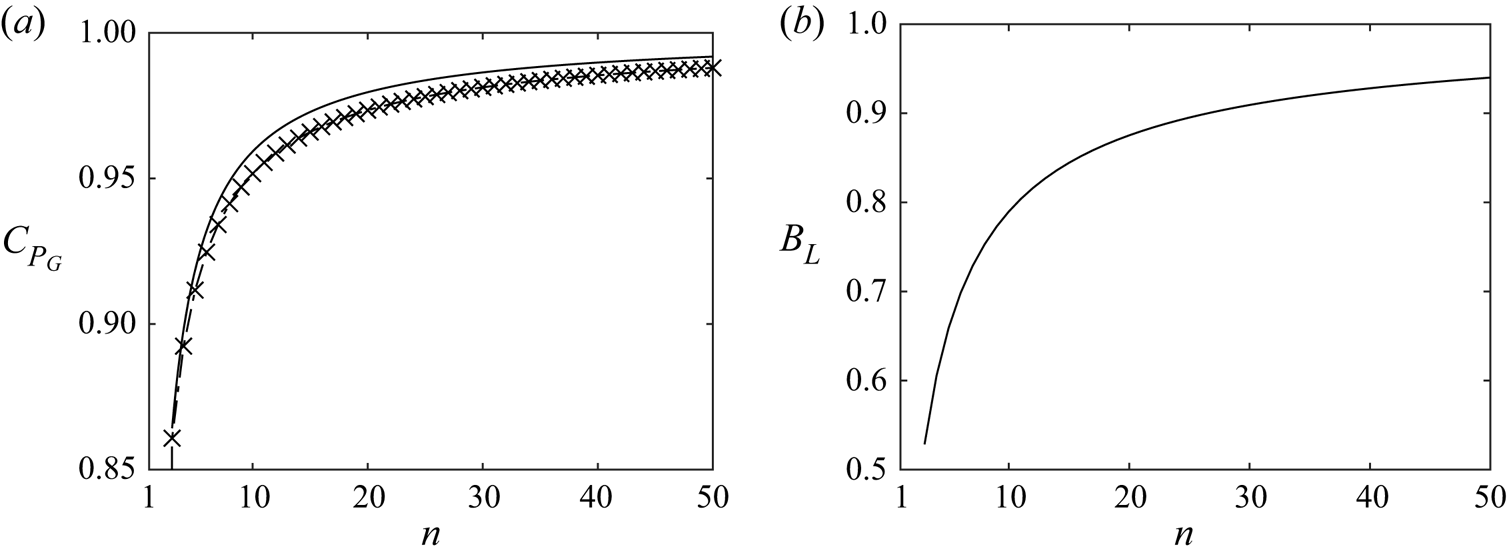
Figure 7. Properties of a fractal multi-scale energy extracting device where the local blockage is held constant for all scales. (a) A comparison of the optimal (solid line) and fractal device energy (crosses) extraction efficiency and (b) the local blockage ratio required for optimal extraction for an  $n$-level fractal device.
Figure 8 further illustrates the relationship between the local blockage ratio (which once again remains the same across scales for the fractal device) and the resultant power coefficient. Given the small under-performance when compared with the optimal configuration, figure 8 condenses the complex multi-dimensional data of the optimal configuration and figuratively describes many of its conclusions. The maximum power extraction efficiency is seen to asymptote to 1 with increasing number of scales. This makes clear the diminishing returns of additional scales, as well as the increasing local blockage ratio required to realise optimal extraction as the layers of the fractal increase. Note that for equally sized discs, the maximum local blockage achievable at the innermost scale is  ${\rm \pi} /4=0.785$ for circular discs arrayed in a rectangular grid, and
  ${\rm \pi} /2\sqrt {3}=0.907$ for circular discs arrayed in rows staggered above and below each other. This provides useful upper physical bounds to the problem indicating that in practical terms no further power coefficient increase can be achieved beyond approximately 10 and 20 fractal layers for rectangular and staggered grid arrangements of equally sized circular actuators.
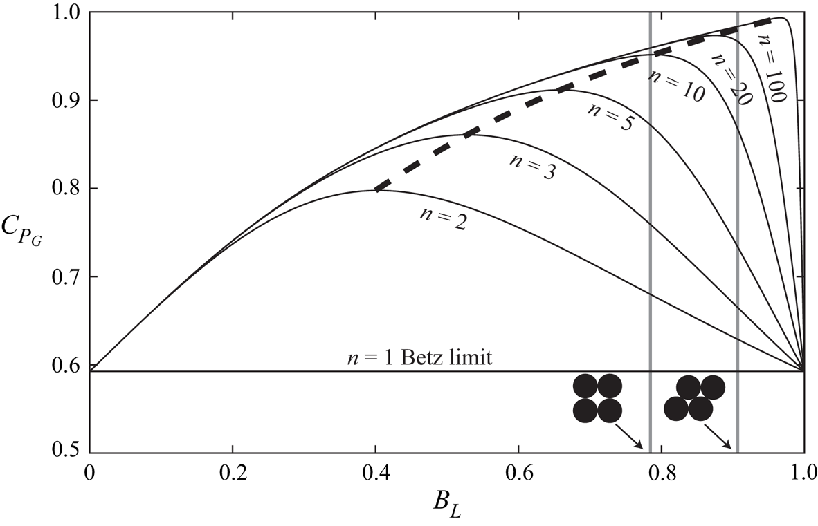
Figure 8. The relationship between local blockage and power extraction for multi-scale fractal devices in an unbounded flow ( $B_n=0$). The dashed line provides the locus connecting the optimal power coefficients for fractal devices up to
  $n=100$ scales. Maximum achievable local blockage ratios are shown for both rectangular
  $(B_L=0.785)$ and staggered
  $(B_L=0.907)$ arrays of equally sized circular discs.
An approximation to the physical arrangement of the discs for the  $n=3$ fractal case is shown in figure 9, which illustrates both the conceptually fractal-like construction of such a device, and the final device with a
  $C_{P_G}\sim 87\ \%$ extraction efficiency (see optimum locus with
  $n=3$ in figure 8). We note that the number of arrays and sub-arrays
  $d_s$ each subsequent fractal iteration splits into would need to be greater than the four shown in the figure to fully realise the extraction limit (see Nishino & Willden (Reference Nishino and Willden2013) for details on the influence of the number of actuators required for a two-scale device).
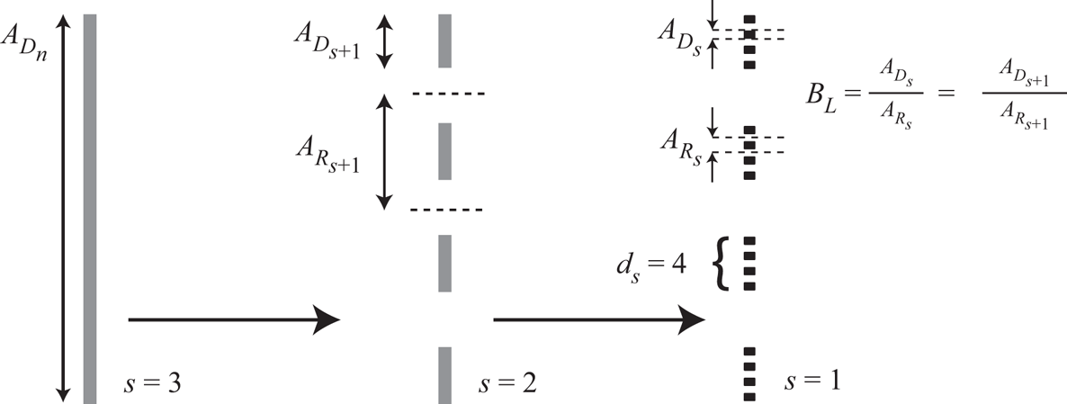
Figure 9. A schematic of a fractal arrangement of discs, which may be visually interpreted by considering the recurrent division of discs into  $d$ new sub-discs per disc with identical spacing between the sub-discs. Here, the array is split
  $n-1=2$ times into
  $d=4$ discs each time, with a constant local blockage ratio of
  $B_L\sim 0.55$, which is near optimal for the fractal arrangement with
  $n=3$. The final arrangement is shown in black.
3.4. Properties of optimal unbounded finite-scale devices
Although an optimal pressure coefficient is only realised for an infinite number of scales, the maximum power coefficient (see figure 3) rapidly asymptotes to the optimal condition for relatively small  $n$. Furthermore, in practice, it appears likely that the maximum number of scales will be limited to small
  $n$. This section therefore considers comparisons of parameter distributions for finite
  $n$, to highlight the differences in these distributions prior to convergence.
Figure 10(a,b) illustrates the velocity factor distributions across scales for various  $n$. For increasing numbers of device scales, the velocity factors always increase at any given normalised scale, with
  $\alpha _s$ and
  $\gamma _s$ both nearing unity across all scales for
  $n=100$. It is clear that as the number of scales increases, the flow across scales decelerates through each subsequent scale more gradually. The reduction in the differential between core and bypass flow velocities at any given scale minimises mixing losses at that scale, whilst keeping
  $\alpha _G$ as close to 1/2 as possible. For a very small number of scales the flow must be rapidly decelerated to ensure a large enough static pressure drop can occur across the energy extraction device, resulting in substantially larger stream-tube deformation.
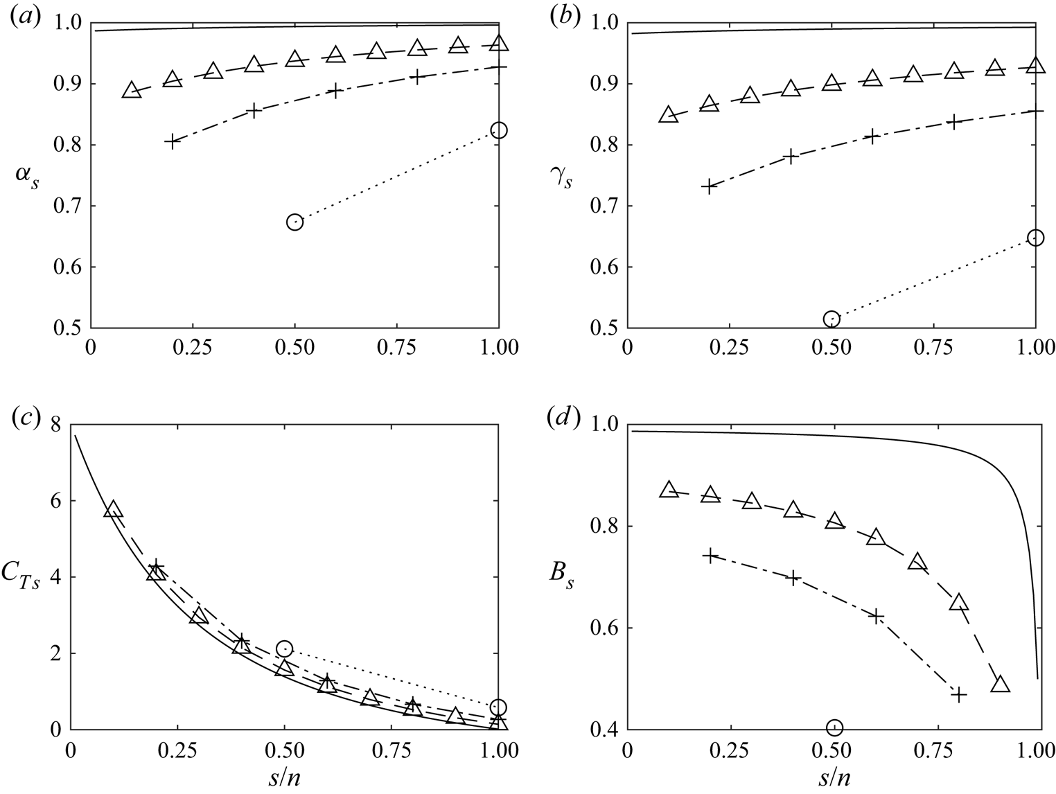
Figure 10. Distributions of (a)  $\alpha _s$, (b)
  $\gamma _s$, (c)
  $C_{T_s}$ and (d)
  $B_s$ for an
  $n = 2$ (circles connected by dotted line),
  $n = 5$ (pluses connected with a dash-dot line),
  $n = 10$ (triangles connected with a dashed line) and
  $n = 100$ (continuous line) multi-scale device for optimal power in an infinitely wide channel
  $B_n = 0$. For clarity, the scale in each device has been normalised by the total number of scales for that device.
Likewise, the thrust coefficient gradually builds up across scales to the smallest (disc) scale (figure 10c) for all numbers of device scales considered. Further, the thrust coefficient distribution appears relatively universal for different numbers of device scales, and approaches the limiting case ( $n\to \infty$) from above as the number of problem scales is increased (i.e. at all normalised scales the thrust coefficient is slightly higher for a lower number of device scales). The physical interpretation of the shape of the
  $C_{T_s}$ curve is analogous to the intuition of the optimum power extraction of the Betz actuator disc model. As a larger thrust is applied to the flow to attempt to increase power extraction, more fluid is ‘diverted’ around the disc. Likewise, with too little thrust, more flow passes through the disc but the power is poorly extracted from the fluid. In the multi-scale device, as
  $n$ becomes larger, the device better decouples these scales such that at the largest scale little resistance is applied to the flow, and at the smallest scale the largest possible resistance is applied to the flow. The near universality of the curve with respect to
  $s/n$ supports the observed higher optimal power coefficient as
  $n$ increases; if the thrust distribution is bound to a universal curve then a greater range of scales from
  $1/n\leqslant s/n\leqslant 1$ is required to achieve greater pressure drop at the smallest scale, and least stream-tube deformation (lowest thrust) at the largest scale. This is achieved as increasing
  $n$ provides greater scale separation along the universal curve, leading to higher optimal power.
The value of  $C_{T_n}$, i.e.
  $C_{T_s}$ at
  $s/n=1$, is observed to decrease as
  $n$ increases (less impact on outermost scale), and so, despite the power extraction efficiency increasing, the impact on global mass-flux reduction is reduced. Interestingly, although the blockage ratios increase at all scales with increasing
  $n$ (figure 10d), the device blockage ratio actually decreases (see figure 11). So that for optimal power extraction in globally unblocked flow, as the number of scales increases, the devices occupy a vanishingly small proportion of the spatial extent covered by the devices.
This is particularly relevant to both tidal (Vennell Reference Vennell2013) and wind (Bleeg et al. Reference Bleeg, Purcell, Ruisi and Traiger2018) energy extraction devices, where the coupling of mass flux and device blockage was observed to play an important role in limiting power extraction. In short, multi-scale devices operating at their optimal energy extraction efficiency, decrease the impact of this detrimental effect. For a fixed channel width, this does, however, come at the expense of reduced power generation, as the discs occupy a smaller fraction of the device area with increasing number of scales. Finally, note that the global thrust coefficient for an  $n=50$-scale device is near
  $2.5$-fold larger than the
  $n=1$ scale device (figure 12), showing that discs need to sustain higher thrust levels for devices with power extraction exceeding the Betz limit.
The distributions of blockage ratios shown in figure 10(d) further relate the geometry of the device to the physics. Note that presently the largest scale is not included, as the blockage for the largest  $n\textrm {th}$-scale is zero by definition. Across the entire
  $s-n$ parameter space, the blockage is bounded by
  $B_s\geqslant 0.4$, with the blockage at the largest interior (
 $n-1\textrm {th}$)-scale converging to 1/2 and at the smallest scale to 1. Similar to the velocity factors, the blockage ratio for a given normalised scale monotonically increases with increasing
  $n$. As in the Garrett & Cummins (Reference Garrett and Cummins2007) model (see Appendix A), blockage at each scale is the physical mechanism by which the velocity factors are modified to optimise the power coefficient of the device. This is clear by consideration of the constraint equation (2.6), whereby the blockage ratio is used to constrain the thrust coefficient rise across scales.
3.5. Finite blockage multi-scale devices
We next consider finite global blockage ratios. For practical purposes we limit our investigation to global blockages less than 0.25. It is not clear that, unless a free surface is introduced into the problem, any new physics emerges for blockages greater than our chosen value.
Figure 13(a) presents the optimal  $C_{P_G}$ for different blockage ratios at different problem scales. Numerical results (indicated by the markers) are compared with an empirical fit given by
 \begin{equation} C_{P_{G, {{Max}}}}
\approx \frac{1}{n} {\left({ 1-B_G }\right)}^{{-}2}
{[{ C_{P,{\textit{Betz}}} + {\left({n-1}\right)}
{\left({ 1-B_G }\right)}^{4/9} }]} ,
\end{equation}
\begin{equation} C_{P_{G, {{Max}}}}
\approx \frac{1}{n} {\left({ 1-B_G }\right)}^{{-}2}
{[{ C_{P,{\textit{Betz}}} + {\left({n-1}\right)}
{\left({ 1-B_G }\right)}^{4/9} }]} ,
\end{equation}
where we note that the leading term  $C_{P,\textit{Betz}} {(1-B_G)}^{-2}$ is the limit determined by Garrett & Cummins (Reference Garrett and Cummins2007) for a (single scale) array of discs homogeneously arrayed across a channel so as to present blockage
  $B_G$. Analogous to the unbounded case, as
  $n \to \infty$,
  $C_{P_{G, {{Max}}}}$ converges to the limit
  ${(1-B_G)}^{-14/9}$, which increases with global blockage as observed in figure 13(a) for
  $n=100$. Even a modest global blockage of 20 % is seen to increase the maximum power coefficient to 1.41 as
  $n\to \infty$. Consequently greater power than the upstream kinetic flux passing through an area equal to the net actuator frontal area may be extracted for
  $B_G > 0$. The relative percentage error between the numerical solution and the empirical fit is shown in figure 13(b) and is below 0.5 % over the range of global blockage ratios and number of scales considered. We conclude therefore that the power coefficient limit for an infinite-scale problem in arbitrary global blockage is then
  $C_{P_{G, {{Max}}}}={(1-B_G)}^{-14/9}$, over the range of global blockage considered herein
  $(0\leqslant B_G \leqslant 0.25)$.
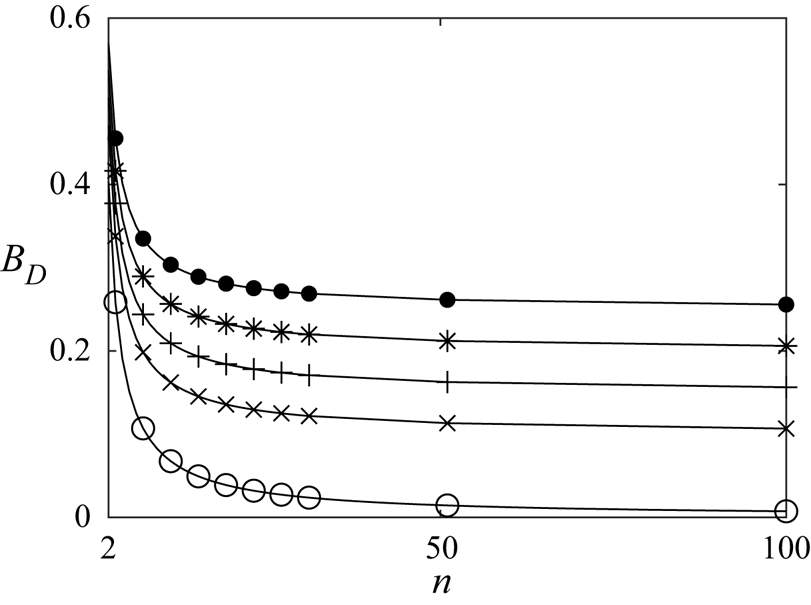
Figure 11. The device blockage ratio  $B_D$ for optimal power as a function of the number of scales of a multi-scale device (markers indicate numerical solutions with circles for
  $B_G = 0$, crosses for
  $B_G = 0.1$, pluses for
  $B_G = 0.15$, stars for
  $B_G = 0.2$ and filled circles for
  $B_G = 0.25$; every fourth simulated data point plotted).
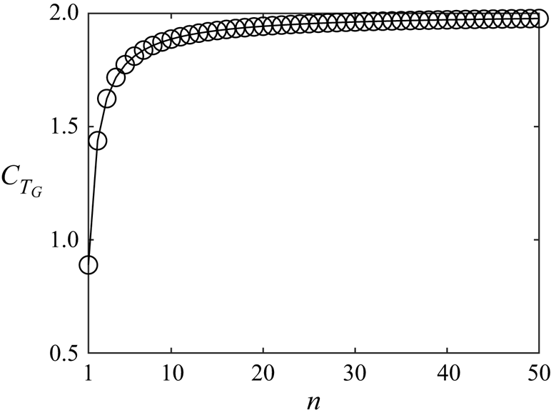
Figure 12. The relationship between global thrust coefficient  $C_{T_G}$ and the number of scales for
  $n\leqslant 50$ for optimal power in globally unblocked flow
  $B_G=0$. The circles indicate the numerical solutions.
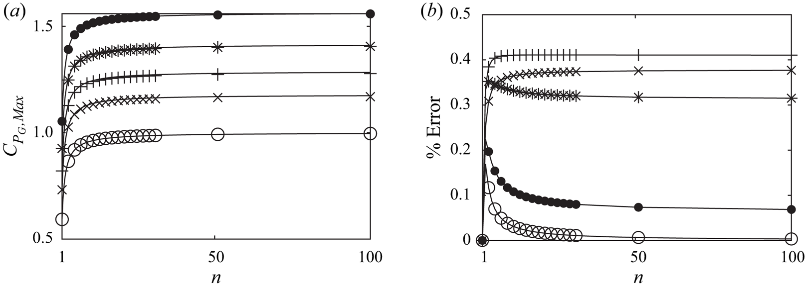
Figure 13. The maximum power coefficient for a multi-scale device with different global blockage ratios (circles for  $B_G = 0$, crosses for
  $B_G = 0.1$, pluses for
  $B_G = 0.15$, stars for
  $B_G = 0.2$ and filled circles for
  $B_G = 0.25$; every other simulated data point plotted), here shown for all scales to
  $n\leqslant 100$. (a) The markers indicate the numerical solutions, and the solid line gives the empirical fit to the optimal
  $C_{P_G}$ (3.13). (b) The relative percentage error between the numerical solution and the empirical fit.
Figure 14 illustrates how different effects contribute to enabling a higher optimal power coefficient. Adding more problem scales can be visualised as a vertical traverse in the direction of the blue arrow, whilst increasing global blockage can be visualised as a horizontal traverse in the direction of the red arrow. Starting at the Betz limit ( $B_G=0$ on the thin continuous line representing a single-scale device), both multi-scale mixing (vertical traverse) or streamwise pressure gradients resulting from finite global blockage (horizontal traverse) may be used to increase the optimal power coefficient. Although it is tempting to think that very high power coefficients in excess of unity may be achievable, in all practical terms global blockages are likely not to exceed
  $B_G\sim 0.1$ aside from at exceptional locations, and it is difficult to see how more than
  $2$ or
  $3$ device scales may be realised. Thus the range of practical importance is confined to the lower left quadrant of figure 14. Nevertheless, this figure provides a useful guide to the interplay between the two effects that serve to increase the optimal energy extraction efficiency.
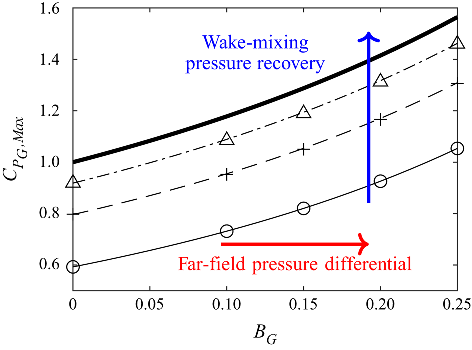
Figure 14. The maximum power coefficient as a function of global blockage (lines indicate the empirical fit (3.13) whilst markers indicate the numerical data points) for an  $n = 1$ (continuous line with circles),
  $n = 2$ (dashed line with pluses),
  $n = 10$ (dash-dot line with triangles) and
  $n = \infty$ (thick continuous line) multi-scale device. Arrows indicate the effects that contribute to an increase in
  $C_{P_G,{{Max}}}$.
The aforementioned decoupling of the inner-scale pressure drop and the outermost scale stream tube modification is also evident for finite global blockage cases. Figure 4(a) shows that, in these cases, the limit for  $\alpha _G$ for large
  $n$ decreases with increasing
  $B_G$ – leading to a higher static pressure drop across the smallest scale – while the stream-tube area remains unmodified (
 $\alpha _n\to 1$ for large
  $n$, figure 4c).
Figure 5 also presents the relevant parameters for an  $n = 100$ multi-scale device with finite global blockages. Compared with the unbounded case the flow is further decelerated across all scales for finite global blockages (figure 5a), which leads to a steeper increase in static pressure towards the smallest scale (figure 5c). The optimal distribution of local blockage ratios on the other hand flattens with increasing global blockage, with even the local blockage at the larger scales approaching near unity. This, together with
  $\alpha _n \to 1$ for
  $n=100$ (figure 4c), infers that even relatively low finite outer-scale blockage is a very effective mechanism to constrain the outer stream-tube and prevent its significant expansion; by contrast, when the flow is globally unblocked, only modest levels of blockage can be imposed across the largest scales so as to limit outer stream-tube expansion (figure 5d). This observation is also captured through examination of the device blockage
  $B_D$ (figure 11); for globally unblocked flows very low device blockage is permissible for optimal power efficiency, and
  $B_D\to 0$ as
  $n\to \infty$, whilst for even small but non-zero outer-scale blockage, significant levels of local blockage
  $B_D\geqslant 0.1$ are permissible at even large
  $n$ for optimal power efficiency. This infers that the optimal energy extractor is far more compact in flows that are constrained at the outermost scale, i.e. for
  $B_n>0$, as compared with globally unblocked
  $(B_n=B_G=0)$ flows.
Finally, we present the parameter distributions and trends across scales for devices of different numbers of scales for  $B_G=0.1$ (figure 15). Generally the results follow those of the unbounded case (figure 10), with slightly reduced velocity factors
  $\alpha _s$ due to the greater upstream deceleration permissible with a finite outer-scale blockage constraint. As already discussed, finite outer scale blockage permits greater local blockage across the scales; compare figure 15(c) with figure 10(c). As in the unbounded case, the local thrust coefficient variation approximately collapses to a single curve with peak
  $C_{T_s}$ at the innermost scale of the device with the largest number of scales. This device local thrust coefficient is then significantly in excess of the limiting value,
  $C_{T_s}=8.0$, for unbounded flows.
3.6. Non-deforming free-surface assumption
We can now consider the implicit assumption that the cross-sectional area of the flow remains approximately uniform, i.e. that the head loss is significantly smaller than the channel depth. The disc configuration shown in figure 2, namely a wide row of discs in a shallow channel where the channel height is smallest, represents the critical case for head loss considerations. Other configurations, such as that shown in figure 1, will be necessarily less restrictive. Although at first it may appear that the bypass flow velocity at the inner scale becomes infinitely large in the limit due to  $B_1\to 1$, we note that actually
  $\beta _1$ remains finite and asymptotic as evidenced by
  $C_{T_1}$ remaining finitely bounded (this can only occur if
  $\alpha _s,\gamma _s\to 1$). At any given scale it can readily be shown by conservation that
  $C_{T_s}=\beta _s^2-\gamma _s^2$. As
  $\gamma _s\to 1$ in the limit of
  $n\to \infty$, this implies that
  $\beta _1$ asymptotes to
  $\beta _1=\sqrt {C_{T_1}+1}$, with figure 16 demonstrating this from the numerical results. As
  $C_{T_s}$ always decreases with increasing
  $s$ (see for instance figure 10), it follows that
  $\beta _1$ will always be the largest bypass flow induction factor, and that the region of flow by-passing the inner disc scale therefore represents the critical spanwise location for maximum head loss in the critical case of the wide and shallow channel realisation of the multi-scale problem. Applying Bernoulli's principle along the bypass, the pressure drop
  $\Delta p_{\infty ,1}$ between the far upstream pressure and the bypass of the innermost scale is therefore
 \begin{equation} \Delta p_{\infty,1} = \frac{1}{2}\rho u_\infty^2\left(\beta_1^2\left(\prod_{i=2}^n\alpha_i^2\right)-1\right) = \frac{1}{2}\rho u_\infty^2\left(\left(C_{T_1}+1\right)\left(\prod_{i=2}^n\alpha_i^2\right)-1\right), \end{equation}
and the head loss is given by  $\Delta h_{\infty ,1} = \Delta p_{\infty ,1}/(\rho g)$. Following Garrett & Cummins (Reference Garrett and Cummins2007), the assumption that the channel cross-sectional area remains unchanged requires that the head loss is significantly smaller than the channel height
  $H$, and so a condition on the Froude number may be formulated as follows:
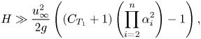 \begin{gather} H \gg \frac{u_\infty^2}{2g}\left(\left(C_{T_1}+1\right)\left(\prod_{i=2}^n\alpha_i^2\right)-1\right), \end{gather}
 \begin{gather}\frac{u_\infty^2}{gH} \ll \frac{2}{\left(C_{T_1}+1\right)\left(\prod\limits_{i=2}^n\alpha_i^2\right)-1}, \end{gather}
 \begin{gather}Fr \ll 2^{1/2}{\left[{\left(C_{T_1}+1\right)\left(\prod_{i=2}^n\alpha_i^2\right)-1}\right]}^{{-}1/2}. \end{gather}
 This condition is well satisfied for tidal flows which typically have Froude numbers in the range of  $0.05\leqslant Fr \leqslant 0.25$, and almost always satisfied for wind farm flows. For instance, for the unbounded case where
  $\prod _{i=2}^n\alpha _i\to 1/2$ and
  $C_{T_1}\to 8$, the condition reduces to
  $Fr \ll 1.26$. For a large global blockage case of
  $B_G=0.25$, where
  $\prod _{i=2}^n\alpha _i\to 0.47$ (see figure 4) and
  $C_{T_1}\to 15$ (see figure 5), the condition reduces to
  $Fr \ll 0.93$. It is clear therefore that the multi-scale model broadly satisfies the non-deforming free surface assumption for modest global blockage ratios. Analogous to the single-scale model of Garrett & Cummins (Reference Garrett and Cummins2007), the validity of this assumption for the multi-scale model is primarily dependent on the global blockage ratio, and is increasingly restrictive as the global blockage increases.
Figure 15. Distributions of (a)  $\alpha _s$, (b)
  $\gamma _s$, (c)
  $C_{T_s}$ and (d)
  $B_s$ for an
  $n = 2$ (circles connected by dotted line),
  $n = 5$ (pluses connected with a dash-dot line),
  $n = 10$ (triangles connected with a dashed line) and
  $n = 100$ (continuous line) multi-scale device for optimal power for a global blockage ratio
  $B_G = 0.1$. For clarity, the scale in each device has been normalised by the total number of scales for that device.
Figure 16. The inner-scale bypass flow velocity  $\beta _1$ for optimal power as a function of the number of scales of a multi-scale device (markers indicate numerical solutions with circles for
  $B_G=0$, crosses for
  $B_G=0.1$, pluses for
  $B_G=0.15$, stars for
  $B_G=0.2$ and filled circles for
  $B_G=0.25$; every fourth simulated data point plotted.
3.7. Numerical demonstration of multi-scale performance uplift
We now present three-dimensional Reynolds-averaged Navier–Stokes (RANS) computations of the  $n=2$ and
  $n=3$ optimal configurations, with the focus on demonstrating both the uplift in power coefficient and scale-separation arguments. We simulate the configuration shown in figure 2, namely a wide row of discs in a shallow channel, where we compare the theoretical results with a set of four configurations (table 1), all with the same global blockage ratio. The methodology closely follows that of Nishino & Willden (Reference Nishino and Willden2013), where the governing RANS equations are solved assuming steady and incompressible flow, and turbulence closure is provided using the
  $k-\epsilon$ model of Launder & Spalding (Reference Launder and Spalding1974) (k being the turbulent kinetic energy density and
  $\epsilon$ the rate of dissipation). The height of the channel is set to
  $1.2D$, where
  $D$ is the actuator disc diameter, and the width of the channel is set such that the global blockage ratio is
  $B_G=0.0785$. The Reynolds number (Re, based on the turbine diameter) is set to be large enough (
 $Re = 1.5\times 10^6$) such that viscous forces are negligible, and the inlet turbulence model quantities are set to be very low (
 $k=1.5\times 10^{-6}\ \textrm {m}^2\ \textrm {s}^{-2}$ and
  $\epsilon = 1.5\times 10^{-10}\ \textrm {m}^2\ \textrm {s}^{-3}$, where the inlet velocity is set to unity). The actuator discs are likewise modelled following Nishino & Willden (Reference Nishino and Willden2013), where a change in momentum flux equal to
  $S_U=K(U_d^2/{2}$), where
  $U_d$ is the local streamwise velocity, is added to the momentum equation at the location of the discs to the momentum equation, and
  $K$ is assumed to be uniform across the surface of all discs. The resultant disc averaged global thrust and power coefficients are then calculated by
  $\langle C_{TG} \rangle =K\langle U_d^2\rangle / u_\infty ^2$ and
  $\langle C_{PG}\rangle =K\langle U_d^3 \rangle / u_\infty ^3$, noting that the reference flow speed is unity and where the angle brackets represent face averaging over all discs. See Nishino & Willden (Reference Nishino and Willden2013) for further details and numerical model validation.
Table 1. Summary of flow configurations studied in the numerical framework.
As demonstrated by Nishino & Willden (Reference Nishino and Willden2013), the performance uplift for this specific configuration of discs is primarily limited by the mixing rate, which can be controlled by variations in the turbulence model coefficient  $C_{\epsilon 1}$ and the number of discs. Here, we leave
  $C_{\epsilon 1}$ at its widely used value of
  $1.44$, although we note that lower values would promote mixing, and choose to vary the number of discs to better isolate the multi-scale effect.
The blockage ratios presented in table 1 are the theoretically optimal blockage ratios for the given global blockage ratio. The  $n=2$-scale studies can be readily compared with those of Nishino & Willden (Reference Nishino and Willden2013). The
  $6$-group
  $n=3$ study can be readily compared against the
  $6$ disc
  $n=2$ study, and the
  $240$ disc
  $n=3$ study can be compared against the three-scale theoretical optima.
The summary plot in figure 17 clearly demonstrates the uplift in performance and provides numerical validation for the theoretical model. The  $n=2$ device optima fall between the single-scale (Garrett & Cummins Reference Garrett and Cummins2007) limit and the theoretical two-scale limit. As anticipated, the fence underperforms the theoretical limit due to finite fence length effects, with the
  $48$ disc fence significantly outperforming the
  $6$ disc fence. For
  $48$ discs, the three-scale optimal configuration very slightly outperforms the two-scale
  $48$ disc configuration; this is the result of the interplay between compounding of deleterious finite fence effects with only
  $8$ discs at the inner scale and
  $6$ discs at the outer scale, and uplift due to the additional scale. Finally, for a large number of discs, it is clear that the three-scale array outperforms the two-scale arrays, and the efficiency instead approaches the three-scale theoretical limit.
The assumption underpinning the theoretical analysis is that of scale separation between each sequential scale. Figure 18 shows how the mixing process across each scale occurs sequentially, and that the far wake mixing of a given scale takes place much faster than the horizontal expansion of the flow around the next scale. For this reason, the near wake (from say  $z/D \sim 5$) of the
  $n=2$ scale simulation resembles a single-scale wake, and the near wake (from
  $z/D \sim 5$) of the
  $n=3$-scale device resembles that of an
  $n=2$-scale
  $6$ disc array (which further mixes to resemble a single-scale wake far downstream). With the aid of figure 17, one can inductively picture how with each additional scale the scale-separation assumption is satisfied. For instance, the near wake of an
  $n=4$-scale device will resemble an array of
  $n=3$-scale devices (with the accelerated bypass between each array) and so forth.
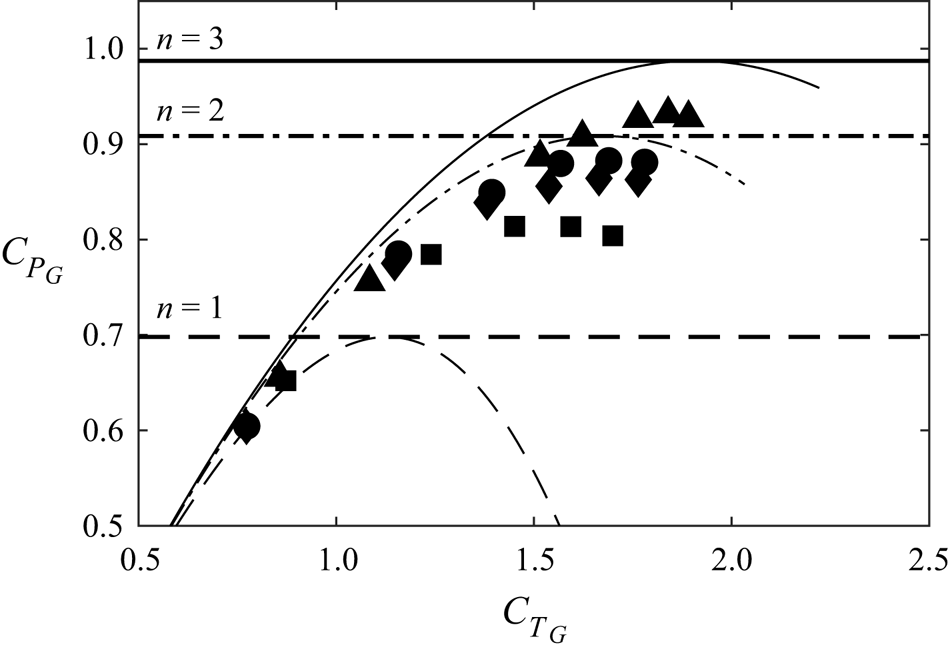
Figure 17. Power curves for the numerical configurations detailed in table 1, illustrating power uplift under multi-scale effects for a global blockage ratio  $B_G=0.0785$. The dashed line shows the single-scale (Garrett & Cummins Reference Garrett and Cummins2007) limit, and the dash-dot and solid lines show both the
  $n=2$ and
  $n=3$ scale limits, respectively, alongside their corresponding power vs thrust variations. Symbols indicate numerical results; squares,
  $6$ disc,
  $n=2$ configuration; diamonds,
  $48$ disc,
  $n=2$ configuration; circles,
  $48$ disc,
  $n=3$ configuration; triangles,
  $240$ disc,
  $n=3$ simulations.
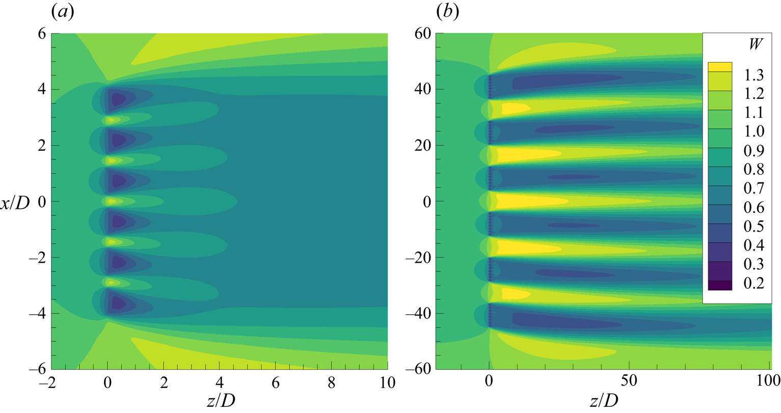
Figure 18. Normalised streamwise velocity field contours at hub height qualitatively illustrating scale separation for the  $6$ disc
  $n=2$ scale (a) and
  $6$ group of
  $8$ disc
  $n=3$ (b) configurations. The flow is moving left to right, with bypass and core flow regions clearly visible. Note the differences in geometric scale between the two simulations.
We note that although the multi-scale shallow water array numerically approaches the theoretical optima, other configurations that encourage wake mixing may also be useful for extracting power above the Betz limit. The theoretical optimum provides an upper bound on the energy extraction efficiency (which will always hold), and sets a benchmark against which the multi-faceted effects of finite mixing lengths, real array inefficiencies, number of devices, turbulence effects and other flow physics can be evaluated.
4. Discussion
We now use the model to hypothesise the physical processes that enable multiple scale disc arrangements to extract more power than single extractors placed in unbounded flow. It is attractive to think, at first, that a higher device energy extraction efficiency from the flow,  $C_{P_G}$, must result from a reduction in losses in the multi-stage process. Within the confines of this model the only energy losses that occur are in the wake remixing processes, and thus one might hypothesise that greater device energy extraction efficiency is a result of reduced mixing losses. In fact, the reverse turns out to be the case.
Consider a multi-scale energy extractor with arbitrary number of scales, for which the global velocity induction factor is  $\alpha _G$. The extractor is placed in a flow of finite dimension so that it presents a non-zero global blockage. We consider the changes between the far upstream and the far downstream location following all necessary flow remixing. As the flow area does not change from far upstream to far downstream there can be no change in momentum or kinetic energy flux. Hence, linear momentum gives that the global thrust on the array,
  $T_G$, is entirely due to the pressure difference from far upstream to far downstream
 \begin{equation} T_G=\Delta p_\infty A_c , \end{equation}
with  $\Delta p_\infty$ the change in static pressure along the stream, and
  $A_c$ the channel cross-section area. We consider the change in total pressure from far upstream to far downstream and hence the total change in energy flux due to both useful energy extraction and remixing
 \begin{equation} \Delta \dot{E}_{05} = \Delta p_\infty A_c u_\infty . \end{equation}
Substituting with the expression from linear momentum enables the change in energy flux to be written in terms of the useful power generated  $P_G=T_G u_\infty \alpha _G$
 \begin{equation} \Delta \dot{E}_{05} = \frac{P_G}{\alpha_G} . \end{equation}
Alternatively we may express this in the form of a basin efficiency,  $\eta$, defined as the ratio of useful energy removed to the total energy removed from the flow
 \begin{equation} \eta= \frac{P_G}{\Delta \dot{E}_{05}} = \alpha_G . \end{equation}
We must be cautious here to distinguish between the actual efficiency of energy extraction from the flow,  $\eta$, and the perceived efficiency of the device,
  $C_{P_G}$, which gives an indication of the density of power extraction at the disc plane.
The expression (4.4) yields the well-known result that for a single unbounded disc operating at the optimal Betz limit, the overall efficiency of energy extraction is  $\eta _{\textit {Betz}}=2/3$. For a single scale of disc (homogeneous array) operating in a blocked flow Garrett & Cummins (Reference Garrett and Cummins2007) showed that optimum
  $C_{P_G}$ is accompanied by a reduction in
  $\alpha _G$ as blockage increases (see also Appendix A), and hence, by the above, the efficiency of energy extraction must also reduce. For multi-scale energy extraction in a vanishing outer-scale blockage, it has been demonstrated that for maximum power coefficient
  $\alpha _G \to 1/2$ as the number of scales
  $n \to \infty$, and to even lower values of
  $\alpha _G$ for non-zero global blockage. Hence, we conclude that to extract higher levels of energy from the flow, the efficiency of energy extraction,
  $\eta$, must be reduced and a greater proportion of the overall energy removed expended on flow remixing. For the specific case of an infinite scale energy extractor operating in a vanishingly small global blockage it follows that at most
  $1/2$ of the total energy removed from the flow will be usefully extracted when the device energy extraction efficiency,
  $C_{P_G}$, is maximised.
We next seek a physical explanation of how scale remixing enables an increase in pressure jump and hence power extraction across the disc plane. Consider the process of mixing two streams of the same incompressible fluid moving at different velocities but with the same initial pressure. It can be readily shown through conservation of mass and linear momentum that the static pressure of the fully mixed fluid will increase by  $\Delta p_{mix} \propto \Delta u_{ab}^2$ where
  $\Delta u_{ab}$ is the velocity difference between the two streams
  $a$ and
  $b$. Static pressure increase is therefore an inevitable consequence of incompressible flow mixing processes.
Consider the variation of the static pressure from far upstream to far downstream of a disc or disc array, as illustratively depicted in figure 19. All processes upstream of the disc are inviscid and hence flow deceleration to the disc plane is energy conserving regardless of the number of scales so that the pressure coefficient upstream of disc plane  $c_{pu}=1-\alpha _G^2$ always. The pressure coefficient on the downstream side of the disc plane is more complex due to viscous remixing processes and the streamwise pressure gradient associated with outer-scale blockage. In the case of a single-scale unbounded energy extractor the pressure coefficient downstream of the disc plane is given by
  $c_{pd}=\gamma _G^2-\alpha _G^2$. The power extracted by the disc or disc array may be expressed in terms of the change in pressure coefficient through
 \begin{equation} C_{P_G} = \alpha_G {({ c_{pu}-c_{pd} })} . \end{equation}
Hence, for the optimally operated single unbounded disc the pressure coefficient rises to  $5/9$ ahead of the disc and falls to
  $-1/3$ immediately after. For the case of the unbounded
  $(B_n\to 0)$ infinite-scale extractor
  $\alpha _G \to 1/2$ for optimum extraction and so
  $c_{pu}-c_{pd} \to 2$. The rise in upstream pressure is limited by the change in
  $\alpha _G$ to
  $c_{pu} \to 3/4$, and so a downstream pressure coefficient
  $c_{pd} \to -5/4$ is needed to achieve the pressure balance required for
  $C_{P_G, {{Max}}} \to 1$.
This low level of downstream pressure cannot be sustained if the flow is to recover inviscidly to free-stream conditions, and additional mechanisms are required to increase the flow pressure through recovery. This is the role of bypass flow mixing which acts to increase the static pressure in the recovery enabling a lower pressure to be maintained immediately downstream of the discs. As depicted in figure 19 we may visualise each remixing processes that the flow undergoes in the wake as being a bypass propeller that imposes a streamwise thrust on the flow,  $T_{b_s}$, that injects additional momentum into the core flow through mixing with the bypass flow at scale
  $s$. The thrust exerted on an unbounded
  $n$-scale device is then given by
 \begin{equation} T_G = \dot{m}_t u_\infty {\left({ 1-\gamma_n }\right)} + \sum_{s=1}^{n-1} T_{b_s}, \end{equation}
where  $T_{b_s}=\dot {m}_{b_s} u_\infty {({ 1-\gamma _n })}$, and
  $\dot {m}_t$ and
  $\dot {m}_{b_s}$ are the mass fluxes through the disc core flows and the bypass of scale
  $s$. Conceptually every additional bypass mixing process that is added provides a pressure rise in the wake which may be visualised as an additional propeller thrust
  $T_{b_s}$. Each propeller thrust enables an additional equal and opposite thrust increment to be developed at the disc plane. Hence, any process that forces wake flow remixing is able to develop an increased pressure drop across the disc plane and exceed the single-scale energy extraction limit. As more scales of mixing are added the pressure recovery that may be supported through the wake increases, leading to increased energy extraction.
Nishino & Willden (Reference Nishino and Willden2012a) observed from numerical simulation that the performance of single actuator discs in blocked flows could be enhanced through turbulent wake mixing processes. This is consistent with the above argument, so that increasing the rate of mixing through turbulence leads to additional wake pressure recovery through the disc wake, and thus greater pressure drop across the actuator itself.
The above remixing argument applies equally to unbounded as well as finite outer scale blockage flows. In the case of the latter an additional streamwise pressure change occurs from far upstream to far downstream of the flow. This pressure change,  $\Delta c_{p_\infty }$, is readily understood and is the pressure change that results from any resistive force applied to a constrained flow. In terms of the pressure development through the flow the effect of finite outer-scale blockage on single-scale energy extraction can be visualised as the ability to reduce the pressure on the downstream side of the extractor so that
  $c_{pd,B_G\neq 0}< c_{pd,\textit{Betz}}$, as well as to increase the pressure coefficient achievable on the upstream side of the extractor. Multi-scale energy extraction and the necessary flow remixing processes provide additional recovery in the wake flow so that an even lower pressure can be achieved immediately downstream of the discs
  $c_{pd,MS,B_G\neq 0}< c_{pd,B_G\neq 0}$ for optimum extraction.
The two processes of finite outer-scale blockage leading to changes in far-field pressure conditions, and flow-scale remixing leading to additional wake pressure recovery, are of course interlinked, if not only through the upstream flow deceleration which both mechanisms affect. It is, however, instructive to decompose a general multi-scale finite blockage problem into these mechanisms and visualise the potential effects of each mechanism on maximum extractable power as illustrated in figure 14.
5. Conclusions
This paper extends the two-scale partial fence model of Nishino & Willden (Reference Nishino and Willden2012b) to an  $n$-scale energy extraction model. The extended model uses actuator disc theory to model the energy extractors, assumes scale separation between each subsequent sub-scale, and solves
  $n$ quasi-inviscid problems with kinematic and dynamic coupling between each scale interface. The
  $n$-scale problem is solved by applying a Lagrange multiplier constraint based method to solve blockage constrained flows. The validity of the method is demonstrated through an analytical solution of Garrett & Cummins (Reference Garrett and Cummins2007) single scale constrained actuator disc problem. Both actuator disc theory and assumptions of scale separation are approximations to the real fluid mechanics but have been shown to be useful in understanding energy conversion from a flow. The presented analysis adds more ‘scales’ than previous studies, but purely in terms of the fluid mechanics, makes no additional assumptions.
A simple approximate analytical expression for the maximum power coefficient as a function of the number of scales of the device is presented,  $C_{P_{G},{Max}}=1+(C_{P,\textit{Betz}}-1)/n$, and it is shown that the theoretical limit to power extraction for any energy extracting device in an unbounded fluid is bounded by
  $C_{P_G}=1.0$, a
  $27/16\sim 70\ \%$ increase on the Betz limit. The
  $n$-scale device is shown to approach this new true upper bound for unblocked flow energy extraction with increasing
  $n$, recalling that the upstream flow is assumed unperturbed by the device. This is physically achieved through using the intermediate scales to help to decouple the outermost device (largest) scale physics, where the area of the stream-tube is left unmodified, and the innermost disc/energy extraction (smallest) scale physics, where the static pressure drop across the disc is optimal. Taken another way, the results suggest that a single device should not have uniform resistance across its area – instead, it should introduce a near fractal distribution of resistance across its surface in order to achieve maximum power generation per area of active extractor.
Distributions of the local blockage ratios and velocity tuning factors across scales for a near optimal energy extraction device are presented, with a key result illustrating the gradual deceleration of the flow across each subsequent scale, alongside the gradual build-up of the static pressure. For optimal extraction, the flow decelerates by a factor of near 1/2 of the upstream velocity at the disc extraction plane, depending on the number of device scales. Further, for globally unblocked flow, as the number of device scales increase, the device blockage (ratio of total disc area to the flow passage area of the outermost device scale) decreases, tending to 0 as  $n\to \infty$; that is, although disc efficiency may increase with increasing
  $n$, the discs themselves must become vanishingly small (or the channel infinitely large) to achieve this. Additionally, as device blockage tends to 0 for optimal extraction at large number of device scales, there is no detrimental reduction of the mass flux through the system which could potentially reduce the extractable power. We further show that the optimal distribution of blockage to achieve optimum power extraction in unblocked flow is well approximated by a fractal multi-scale device; that is a device in which local blockage at all consecutive scales is equal.
As in the Garrett & Cummins (Reference Garrett and Cummins2007) single-scale model, the addition of finite global (outer scale) blockage is shown to further increase the optimal power coefficient of a multi-scale device above 1. We provide an empirical fit to the computed optimal global power coefficient,  $C_{P_{G, {{Max}}}} \approx {(1/n)} {({ 1-B_G })}^{-2} {[{ C_{P,{\textit{Betz}}} + {({n-1})} {({ 1-B_G })}^{4/9} }]}$, that accounts for both the number of device scales as well as the overall global blockage,
  $B_G$. This expression is shown to be accurate for the range of practical global blockage ratios (including unblocked flow) considered herein.
Contrary to what one might intuitively think, we show that the minimisation of mixing losses is not the mechanism by which the power extraction increases with number of scales. In fact, wake mixing provides an additional source of static pressure rise in the device wake that enables additional reduction in static pressure on the downstream side of the extractor, and consequently an increase in the static pressure drop across the device, leading to increased power extraction. For the specific case of globally unblocked flow we show that at most  $1/2$ of the total energy removed from the flow can be usefully extracted when the device power coefficient is maximised, with the remaining
  $1/2$ energy removed lost in wake remixing. This contrasts to the
  $1/3$ energy that is lost in wake remixing by a single disc operating at the Betz limit in unblocked flow. We draw distinction between device efficiency, i.e. power coefficient, and overall energy extraction efficiency, i.e. basin efficiency, and observe that as the former increases the latter necessarily decreases.
For devices placed in a finite width channel, the streamwise pressure drop that must occur to balance device thrust enables a reduction in the pressure on the downstream side of the extractor, again providing the basis for increased power extraction. The two mechanisms to decrease the pressure on the downstream side of the extractor are shown to be additive so that multi-scale devices placed in bound flows can experience even higher levels of power extraction through wake remixing pressure recoveries and overall streamwise pressure drops between far-field conditions.
Both multi-scale interactions and global blockage further decelerate the flow upstream of the disc, raising the upstream static pressure and consequently increasing the extractable power. The optimal arrangement of discs changes with global blockage to account for the additional deceleration that global blockage causes, with the blockage ratios at the largest scales increasing significantly from those of the unbounded extractor.
We have demonstrated numerically, using large actuator disc simulations in a RANS framework, that by increasing the number of scales from two to three that the power delivered by the array can be increased beyond that that can be achieved for the same finite number of discs at two scales with global blockage preserved.
Realistically for wind or tidal power applications, separating the flow into more than a few scales does not appear feasible, and achieving very high levels of global blockage, perhaps maximum  $B_G \sim 0.1$, unachievable without serious environmental impact. The physical space of realistic exploitation is thus confined to the bottom left quadrant of figure 14, but if properly designed for and managed, some plausible, yet significant, increases in power coefficient through blockage and use of scale remixing are possible.
This article provides the first theoretical construction of an arbitrary multi-scale optimal energy extraction device in a steady flow, and presents a theoretical upper bound on its energy extraction. One of the primary conclusions of the paper is that wake mixing is responsible for sustaining low pressure on the downstream side of the actuator disc. Whilst the multi-scale array demonstrates that this may be achieved through recursive scale-to-scale wake mixing events, other configurations that encourage wake mixing may also be useful for extracting power above the Betz limit. Innovative devices that exploit the same physical processes without the use of multi-scale mechanisms may prove a fruitful avenue for future exploration. Our limiting cases use an infinite number of scales which can never be possible in a finite universe. Whilst this is a theoretical model, we hope this work may provide the scientific basis for others to innovate.
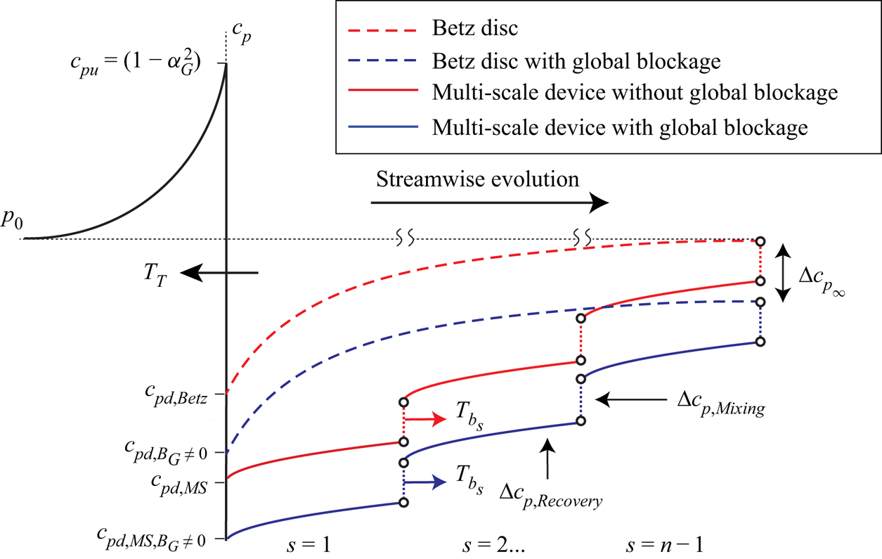
Figure 19. A schematic illustrating the impact of mixing in the wake of each scale of the multi-scale extractor. The curves represent the pressure of a given fluid particle as it travels through the scales from the undisturbed upstream conditions through the different models to the far wake. The mixing corresponds to pressure increases at each scale in the wake allowing for greater energy extraction across the disc plane. Global blockage allows for additional pressure extraction through a change in the pressure boundary condition in the far wake.
Funding
The authors would like to acknowledge the support of funding bodies as follows: D.D. is funded by an EPSRC studentship, grant number EP/S023801/1, and R.H.J.W. is supported by an EPSRC Advanced Fellowship EP/R007322/1 and by the EPSRC Supergen ORE Hub, grant number EP/S000747/1.
Declaration of interests
The authors report no conflict of interest.
Appendix A. Blocked flow past a homogeneous turbine array
Although Garrett & Cummins (Reference Garrett and Cummins2007) numerically demonstrated that the Betz limit is increased by a factor  $(1-B)^{-2}$ for a single or homogeneous array of turbines that present a blockage
  $B$ within a confined channel, there has yet to be an analytical verification of this key result in the literature. This section provides a re-framing of the flow problem as a nonlinear constrained optimisation problem, that allows both an analytical verification of the key result, and sets the context in which the multi-scale flow problem is solved.
Consider the control volume shown in figure 20, where the bulk flow is split by the stream tube into the fluid flowing through the turbine (or homogeneous turbine array) and the fluid bypassing the turbine. By separately applying conservation of mass, momentum and energy to the two flow regions, the following relationship between the bypass and core flows can be derived (Garrett & Cummins Reference Garrett and Cummins2007):
 \begin{equation} \gamma^2 B + 2\gamma (\beta-1)+(\beta-1)^2-B\beta^2=0, \end{equation}
where the turbine power coefficient  $C_P=P/(1/2 \rho u_1^3 A)$, with
  $P$,
$P$,  $A$ and
  $u_1$ the turbine power, swept area and undisturbed upstream velocity respectively, can be shown to be
 \begin{equation} C_P = (\beta+\gamma)(\beta-1)\frac{\gamma}{B}. \end{equation}
Spurious solutions are identified by considering the physical constraints
 \begin{gather} 0 < \gamma \leqslant 1, \end{gather}
 \begin{gather}1 \leqslant \beta < \infty, \end{gather}
 \begin{gather}0 \leqslant B \leqslant 1. \end{gather}
To analytically determine the maximum  $C_P$, these equations are re-cast in constrained optimisation form, where we are interested in maximising equation (A2) subject to the constraint equation (A1). Consider, therefore, the Lagrangian
 \begin{equation} \mathcal{L} = (\beta+\gamma)(\beta-1)\frac{\gamma}{B} + \lambda [\gamma^2 B + 2\gamma (\beta-1)+(\beta-1)^2-B\beta^2 ], \end{equation}
for which the stationary points are identified by
 \begin{equation} \boldsymbol{\nabla}_{\beta,\gamma,\lambda} \mathcal{L} = 0. \end{equation}
The following system of equations can then be solved for  $\beta ,\gamma$ and
  $\lambda$ as a function of the blockage
  $B$ for the optimum, where the physical constraints (A3)–(A5) once again identify spurious solutions:
 \begin{gather} \frac{\gamma(\beta-1)+\gamma(\gamma+\beta)}{B} + \lambda(2\gamma+2\beta-2B\beta-2) = 0, \end{gather}
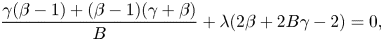 \begin{gather}\frac{\gamma(\beta-1)+(\beta-1)(\gamma+\beta)}{B} + \lambda(2\beta+2B\gamma-2) = 0, \end{gather}
 \begin{gather}(\beta-1)^2 + B\gamma^2 - B\beta^2 + 2\gamma(\beta-1) = 0. \end{gather}
A trivial solution may first be found by setting  $\lambda$ to 0, giving
  $\gamma =-1$ and
  $\beta =1$. The non-trivial solutions involve considerable algebraic complexity with solutions in the form of roots of quartic equations. If one considers the physical constraints (A3)–(A5), however, there is only one solution to the stationary points of
  $\mathcal {L}$.
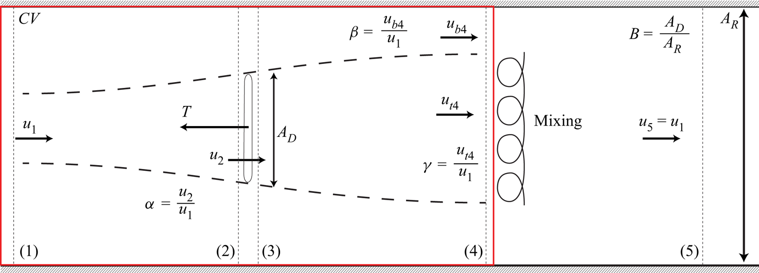
Figure 20. A schematic of an energy extracting actuator disc in a constrained channel (Garrett & Cummins Reference Garrett and Cummins2007). The schematic shows the control volume taken for the quasi-one-dimensional analysis, with the non-dimensional velocity factors  $\alpha$,
  $\beta$,
  $\gamma$ and the blockage ratio
  $B$ characterising the flow problem.
Re-arranging (A9) for  $\lambda$ and substituting into (A8) gives
 \begin{align} \frac{\gamma(\beta-1)+\gamma(\beta+\gamma)}{B}-\frac{(2\gamma+2\beta-2B\beta-2)(\gamma(\beta-1)+(\beta-1)(\beta+\gamma))}{B(2\beta+2B\gamma-2)}=0. \end{align}
Multiplying through by  $B$, multiplying out the fraction and collecting in terms of
  $\beta$ yields
 \begin{align} &\beta^3(B-1)+\beta^2(2B\gamma+2-B-\gamma)+\beta(2B\gamma^2+2\gamma-2B\gamma-\gamma^2-1) \nonumber\\ &\quad + B\gamma^3-B\gamma^2+\gamma^2-\gamma=0, \end{align}
which factors into a product of two terms
 \begin{equation} (B\gamma+\beta(B-1)+1)(\beta^2+\beta(\gamma-1)+\gamma^2-\gamma)=0, \end{equation}
with the three roots therefore being
 \begin{equation} \beta_{1,2,3} = \frac{B\gamma+1}{1-B} \lor \frac{1-\gamma}{2} \pm \sqrt{\frac{(\gamma-1)^2}{4}+\gamma-\gamma^2}. \end{equation}
For the physically possible range of the wake induction factor,  $0 < \gamma \leqslant 1$, the quadratic solutions for
  $\beta$ are
  $0\leqslant \beta _2 < 1$ and
  $\beta _3 \leqslant 0$ which cannot satisfy the physical constraints of mass conservation
  $\beta \geqslant 1$. Hence, only the first non-quadratic solution for
  $\beta$ is physical. Substituting this root into (A10) simplifies to
 \begin{gather}
B\gamma^2-\frac{B({-}B\gamma-1)^2}{(B-1)^2}+2\gamma\left(\frac{-B(\gamma+1)}{B-1}\right)+\left(\frac{-B(\gamma+1)}{B-1}\right)^2=0,\\
(B^2-B)(3\gamma^2+2\gamma-1) = 0,
\end{gather}
\begin{gather}
B\gamma^2-\frac{B({-}B\gamma-1)^2}{(B-1)^2}+2\gamma\left(\frac{-B(\gamma+1)}{B-1}\right)+\left(\frac{-B(\gamma+1)}{B-1}\right)^2=0,\\
(B^2-B)(3\gamma^2+2\gamma-1) = 0,
\end{gather}
which trivially reduces to  $\gamma =1/3$ or
  $-1$, for which the only physical solution is
  $\gamma ^*=1/3$. Further substituting this into (A14) for the first root, followed by substitution into (A8) for
  $\lambda$ returns the optimal solutions, namely,
 \begin{equation} \gamma^* = \frac{1}{3},\quad \beta^*={-}\frac{B+3}{3(B-1)}, \quad \lambda^* ={-}\frac{2}{3B-3B^2}, \end{equation}
which can readily be verified by back substitution into the system of (A8)–(A10).
Evaluating the objective function (A2) at this point gives analytical verification that the numerical result of Garrett & Cummins (Reference Garrett and Cummins2007) is exact,
 \begin{equation} C_{P_{Max}} = (\beta^*+\gamma^*)(\beta^*-1)\gamma^*/B = \frac{16}{27(B-1)^2} =C_{P_\textit{Betz}}\frac{1}{(B-1)^2}, \end{equation}
and that a further key result, namely that  $\gamma ^*=1/3$ irrespective of the blockage ratio, is likewise true.
We draw attention to the relevance of the optimal Lagrangian multiplier
 \begin{equation} \lambda^*=\frac{\textrm{d}C_P^*}{\textrm{d}c}, \end{equation}
where  $c$ is the constraint (A1), which can be physically interpreted as the change of the optimal power coefficient with a relaxation of the constraint. For example, in the case for
  $B=0$, the bypass flow ratio must be exactly
  $\beta =1$ to satisfy the constraint, else the power coefficient will be infinite. The Lagrangian multiplier hence gives indication to the relative importance of the given constraint on the optimal power coefficient, which is relevant to the comparison of the optimal multipliers for the multi-scale device.


